Applications / non-contact thermal spray coatings thickness measurement
01 — Introduction
Thermal spray coatings: the functional skin of modern aircraft
Thermally sprayed coatings are critical throughout the aircraft. Many modern jet engines could not operate at their current efficiency or temperature levels without them, landing gear and actuators rely on them for wear and corrosion resistance, and cold-spray repairs are extending the life of structural components. These coatings act as a functional skin on expensive substrates — nickel superalloys, titanium, high-strength steels, aluminium — protecting them from extreme heat, oxidation, hot corrosion, fretting and sliding wear.
Thermal spray processes used in aerospace
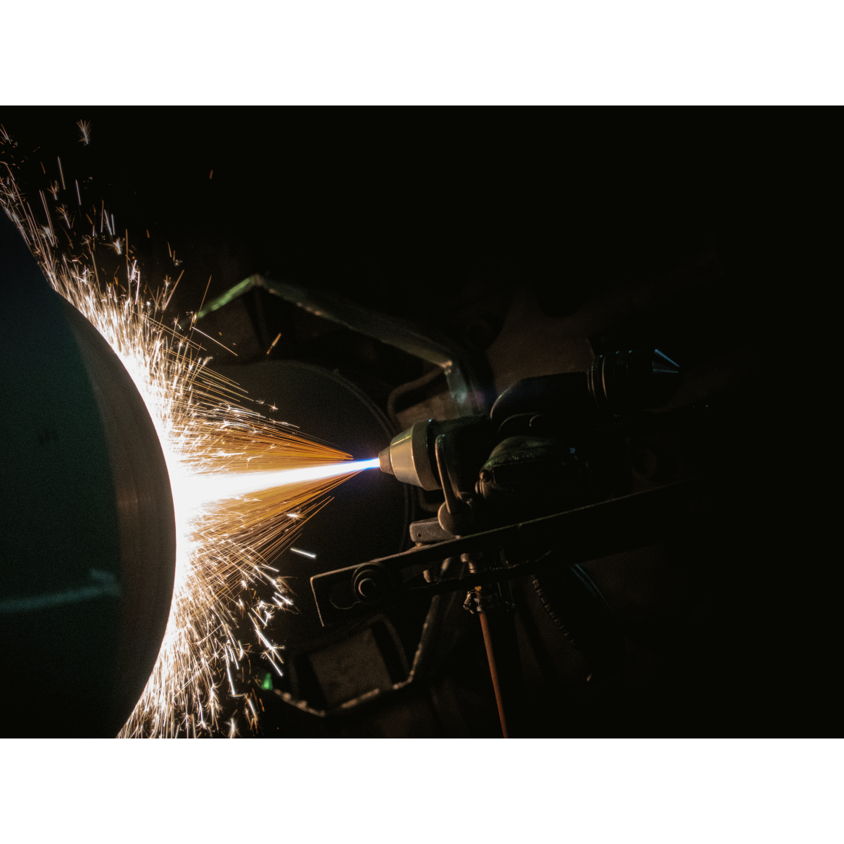
Thermal spraying is a family of coating processes in which finely divided metallic or non-metallic materials are heated to a molten or semi-molten state and propelled at high velocity onto a prepared surface to build a functional layer. The aerospace industry uses several of them depending on the part and the coating material:
Atmospheric plasma spray (APS) HVOF / HVAF Cold spray Wire arc & flame spray Vacuum / low-pressure plasma
- Plasma spray uses a high-energy plasma arc to melt ceramic or metal powders. It is the standard route for thermal barrier coatings (TBCs) on turbine components and for abradable seals.
- HVOF / HVAF propels particles at supersonic speed and builds very dense, tough coatings — typically tungsten-carbide cermets — for wear resistance on landing gear, actuator rods, flap tracks and compressor parts. HVOF WC-CoCr is now the reference replacement for hard chrome plating.
- Cold spray bonds particles through kinetic energy rather than heat. It is increasingly used for dimensional restoration and corrosion repair of structural and housing components.
- Wire arc and flame spray deposit aluminium or zinc-based layers for corrosion protection of structural and ground-support parts.
Figure 1 — Thermally sprayed coating families across the aircraft
Inside the engine: what the coatings do
- Thermal barrier coatings (TBCs) — arguably the most critical coatings in modern aviation. A ceramic top layer, usually yttria-stabilised zirconia (YSZ), acts as a heat shield on high-pressure turbine blades, vanes and combustion liners, allowing gas temperatures above the melting point of the metallic components. A well-applied TBC creates a temperature drop of up to 300 °C across its thickness.
- Wear and fretting-resistant coatings — extremely hard cermets (tungsten carbide-cobalt) or hard alloys (Tribaloy) on blade roots, bearing journals and flap tracks. They prevent fretting, the wear caused by microscopic vibrations at joined interfaces.
- Environmental and corrosion coatings — MCrAlY alloys (M = Ni and/or Co) on compressor blades and as turbine bond coats, protecting against hot corrosion and oxidation in the aggressive, fast-moving engine environment.
Figure 2 — Typical thermal barrier coating system (schematic)
02 — Quality Requirements
Why thickness is the critical metric of a thermally sprayed coating
Coating thickness is the primary bridge between design theory and real-world performance: it is the parameter the designer specifies, the sprayer controls and the inspector must verify. On aerospace parts it is also a safeguard against catastrophic failure.
Too thin: loss of protection
A TBC that is too thin fails to provide the specified thermal gradient, exposing the superalloy to overheating, rapid oxidation and creep. A wear coating that is too thin on a landing-gear piston or flap track wears through before the next overhaul; a corrosion coating that is too thin leaves the substrate unprotected. In every case the part does not reach its design life.
Too thick: internal stress and spallation
Thermally sprayed coatings harbour residual stresses from the rapid solidification of each splat. Combined with the thermal-expansion mismatch between a ceramic layer and a metallic superalloy, an over-thick coating can crack, peel or spall — flaking off the turbine blade in service. On dense HVOF cermets, excessive thickness increases the risk of delamination under cyclic load and adds grinding time and cost.
Uniformity: efficiency and balance
Beyond safety, thickness control drives aerodynamic efficiency. In abradable seals, even a micron-level deviation increases the tip gap and wastes fuel and thrust. Non-uniform coatings on rotating parts create centrifugal imbalance that induces high-cycle fatigue and vibration. Uniformity across the whole coated area — not just the mean value — is therefore part of the specification.
|
up to 300 °C
Temperature drop across a well-applied thermal barrier coating
|
50 – 450 µm
Typical thermal barrier coating thickness range — fully covered by the Enovasense sensors
|
|
0.5 – 3 %
Typical repeatability and intercomparison RMS error of laser photothermal radiometry, relative to the measured thickness
|
< 1 s
Typical non-contact measurement time per point — compatible with mapping and in-process control
|
03 — Measurement Challenges
Why thermally sprayed coatings defeat conventional gauges
Besides destructive cross-section microscopy, the conventional non-destructive options are contact gauges — eddy current, magnetic induction and ultrasonic. On aerospace thermal spray they face four structural limitations.
Material constraints
Magnetic induction requires a non-magnetic coating on a ferromagnetic substrate; eddy currents require a non-conductive coating on a non-ferrous metal. Aerospace stacks rarely fit: MCrAlY on superalloy puts a conductive coating on a conductive substrate; WC-Co and Tribaloy cermets are partly conductive and partly magnetic; MCrAlY and its substrate have near-identical acoustic impedances, so ultrasound sees no interface at all.
The roughness bias
Thermally sprayed coatings are rough and porous by nature. A contact probe rests on the highest peaks of the surface, so it reads the distance from the peaks to the substrate and systematically overestimates the average thickness. The thinner the coating and the rougher the surface, the larger the bias.
Figure 3 — Contact probe on peaks vs averaged non-contact laser spot
Accessibility and geometry
Contact techniques need a flat, stable footprint. That rules out the areas that matter most: inside cylinders and bores, between turbine blades, on the sharp leading edge of a turbine tooth, close to holes and edges where eddy-current readings drift, or on the curved shoulder of an actuator rod.
Reliance on destructive testing
Because of these limits, specialists often fall back on cross-sectioning sacrificed parts or witness coupons — slow, costly, and affected by representativity bias: the coupon is not the part, and the sectioned location is not the whole coated area.
04 — Technology Comparison
Why laser photothermal radiometry fits aerospace thermal spray
Enovasense’s patented laser photothermal radiometry (LPTR) works in four steps: a power-modulated laser beam heats the coating surface by a few degrees; the thermal wave diffuses into the coating and is partially reflected at the coating–substrate interface; an infrared detector collects the thermal flux returning from the surface; the phase shift between the laser modulation and the thermal response is converted into thickness. As long as the laser can heat the material, the sensor gets a response — there is no conductivity, magnetism or acoustic-impedance condition on the coating or the substrate.
For rough, porous thermal spray this brings a decisive property: the measurement is averaged over the laser spot (0.8 to 10 mm), so it reflects the true functional volume of the layer rather than the height of a few peaks. The probe sits 20 or 40 mm from the part, so it is contamination-free and tolerant to distance and angle variations.
| Criteria | Enovasense laser photothermal | Eddy current / magnetic induction | Ultrasonic testing |
|---|---|---|---|
| Measurement principle | Thermal diffusion response | Electromagnetic field interaction | Time-of-flight of sound waves |
| Contact | Non-contact — 20 / 40 mm stand-off | Contact | Contact + couplant |
| Operator influence | Independent | Dependent — how contact is applied | Dependent — how coupling is applied |
| Roughness bias | None — averaged over the spot | Overestimates — probe rests on peaks | Coupling issues on rough surfaces |
| Recalibration | Stable — no time-based drift | Regular | Regular |
| Shape, edge and size dependency | Independent of curvature and geometry | Shape dependent — not near edges and holes | Shape dependent — not near edges and holes |
| Thermal barrier coatings (YSZ, 50–450 µm) | Yes | Yes — with peak bias | No on this range |
| Wear & fretting cermets (WC-Co, Tribaloy) | Yes | Difficult — partly conductive, partly magnetic | No on low thicknesses |
| MCrAlY environmental coatings | Yes | Difficult — conductive on conductive | No — same acoustic impedance |
| HVOF WC-CoCr on steel (landing gear) | Yes | Difficult — cermet on ferromagnetic steel | Limited — thin, dense layers |
Typical performance of laser photothermal radiometry
The measurable thickness ranges from 10 nm to about 1 mm depending on the coating material. Repeatability and intercomparison RMS error typically fall between 0.5 and 3 % of the measured thickness:
| Measured thickness | Typical RMS precision |
| 1 mm | 5 – 30 µm |
| 100 µm | 0.5 – 3 µm |
| 10 µm | 0.05 – 0.3 µm |
| 1 µm | 5 – 30 nm |
Performance depends on the optical system selected, the coating material and the thickness range. Figures presented at ITSC 2026 (Bangkok).
05 — Metrological Performance
Case study: APS yttria-stabilised zirconia thermal barrier coatings
The feasibility study was performed on four flat coupons coated with YSZ deposited by atmospheric plasma spray (APS), with thickness levels from 86 µm to 374 µm. Each coupon measured 10 × 10 mm, so some deposition inhomogeneity was expected within each sample.
An Enovasense Point sensor was used with the following parameters: 980 nm wavelength, 10 W maximum laser power, 1.7 s measuring time, 35 mm probe-to-part distance and a 3.3 mm laser spot. The spot size was chosen large enough to average the sub-millimetric thickness variations inherent to the thermal spray process. The sensor was mounted in a 3-axis control station and a 2D map of each coupon was acquired with a 1 mm step in both directions.
Figure 4 — Thickness maps of the four YSZ-coated coupons (Point sensor, 1 mm step)
Schematic rendering of the Enovasense mapping of the four 10 × 10 mm APS-YSZ coupons. Each cell is one measurement point. Thinner edges correspond to the spray overspray zone at the coupon borders.
Correlation with eddy-current readings
The photothermal maps were correlated with eddy-current readings taken at 10 positions per coupon. For both technologies, the mean value and the standard deviation per coupon were used for the intercomparison.
Figure 5 — Laser photothermal vs eddy current, YSZ coating thickness
Mean thickness per coupon, both techniques; bars show ±1 standard deviation. Eddy current sits slightly above the 1:1 line on every coupon — the peak effect of a contact probe on a rough APS surface.
A 99.5 % correlation is observed between the two techniques. Eddy current tends to slightly overestimate the YSZ thickness because of the peak effect described above, and the laser photothermal measurements show a lower standard deviation than the eddy-current readings on every coupon.
From flat coupons to real geometry: the turbine tooth
The main advantage of laser photothermal radiometry is that it transfers directly from coupons to real parts, since there is no contact and no influence of curvature or proximity to an edge. The turbine tooth is the extreme case: a thermal barrier coating of at least 100 µm is deposited on a sharp area smaller than 1 mm at the top of a very thin tooth — unmeasurable for most coating-thickness technologies.
With the Enovasense Field sensor, the whole tooth is mapped in a 1-second shot at 55 µm spatial resolution, quantifying the coating thickness locally at every position, including the sharp tip.
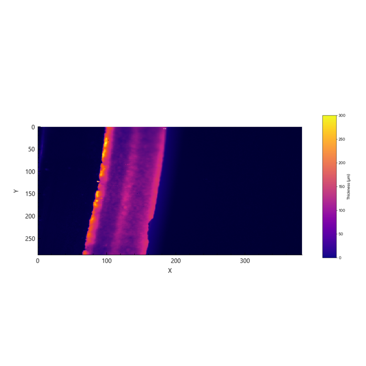
Coating thickness map of a turbine tooth captured with the Enovasense Field sensor — 55 µm resolution, 1 s acquisition
The same method applies to the other aerospace thermal-spray families — HVOF WC-CoCr on landing-gear steels, MCrAlY bond coats, abradables, cold-spray repairs. Actual performance depends on the optical system selected, the coating material and the thickness range; a dedicated calibration is built per coating–substrate system.
06 — Industrial Integration
Integrating Enovasense sensors in the spray shop
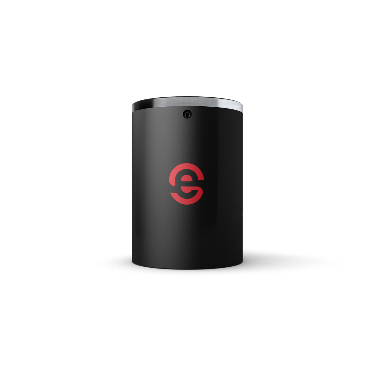
The Enovasense probes are compact and lightweight — typically 35 mm in diameter — and highly tolerant to distance variations (several millimetres at 40 mm stand-off) and to incidence angles of 10° to 40°. They are stable against vibration without precise alignment, and the photothermal calibration does not drift over time. This opens three integration routes.
 |
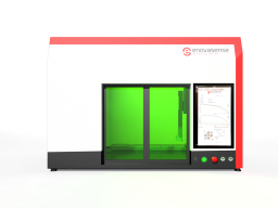 |
| Compact Enovasense probe for robotic integration | HKL2 off-line control station — automated mapping and batch measurement |
References
| Reference | Name | Status / Price | Datasheet |
|---|---|---|---|
| ARTICLE | Non-Contact Thickness Measurement of metallic and ceramic coatings deposited by thermal spray |
Available
On quotation |
English Français |
| APPLICATION NOTE | Controlling the thickness of thermally sprayed coatings |
Available
On quotation |
English Français |
Documents
| Type | Name | Download |
|---|---|---|
| Application | Thermal spray | English Français |
| Application | Controlling the thickness of thermally sprayed coatings | Français |

 English
 Deutsch
 Español
 Français
 Italiano
 日本語
日本語
 Polski
 中文
中文