Applications / non-contact thickness measurement of powder coatings
01 — Introduction
Powder coating: a ubiquitous industrial finishing process
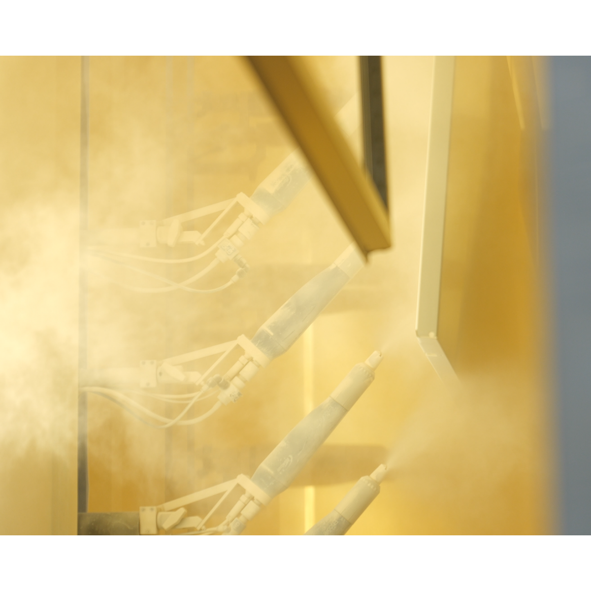
Powder coating — also known as thermolaquage or powder paint — is a dry finishing process applied across a vast range of industries: architectural aluminum (windows, façades, curtain walls), automotive components, home appliances, furniture, electrical enclosures, and general metal fabrication. The process involves electrostatically applying a dry, powdered polymer resin — typically epoxy, polyester, or a hybrid of both — onto a prepared substrate, before curing it in an oven at temperatures between 160 °C and 200 °C to form a hard, smooth, durable layer.
Powder coatings are prized for their excellent mechanical and chemical resistance, their wide color range (several hundred RAL and custom colors are typically offered), and their environmental profile: unlike liquid paints, they contain no solvents and generate minimal VOC emissions. Their durability and aesthetic versatility have made them the finish of choice for architectural aluminum profiles subject to rigorous standards such as Qualicoat, GSB, or EN 13438, as well as for automotive and industrial OEM parts.
Architectural aluminum Automotive parts Home appliances Metal fabrication Electrical enclosures Furniture
A typical powder-coated assembly consists of one or more functional layers. In architectural applications, a zinc phosphate or chrome-free pre-treatment is first applied for adhesion and corrosion protection, followed by a primer layer, and finally the topcoat — the visible layer whose thickness must meet tight tolerances. In demanding environments, a clear varnish over-coat may be added. Total dry film thickness typically ranges from 60 µm to 120 µm, but can reach 200 µm or more for protective or special-effect coatings.
02 — Quality Requirements
Why controlling powder coating thickness is essential
Coating thickness is one of the most critical quality parameters in powder coating. Deviations in either direction have significant consequences for product performance, material cost, and regulatory compliance.
Too thin: protection failures and non-compliance
A layer that is too thin will not provide adequate protection against corrosion, UV degradation, and mechanical abrasion. For architectural aluminum, certifications such as Qualicoat and GSB impose a minimum dry film thickness — typically 60 µm — below which the part cannot be certified. Insufficient coverage also leads to poor hiding power, visible substrate irregularities, and early coating failure in service, generating costly warranty returns and reputational damage.
Too thick: material waste and cosmetic defects
Conversely, an over-applied layer wastes expensive powder — raw material costs represent a major share of the total coating cost, particularly for premium colors and metallic effects. Excessive thickness also risks cosmetic defects such as orange peel, sagging, or surface texture non-uniformity, and can prolong curing time, reducing line throughput. For complex assemblies with tight dimensional tolerances, excess coating thickness can even interfere with fit and assembly.
Consistency: the key to process optimisation
Beyond the binary pass/fail criteria of thickness standards, controlling the layer uniformity across the part surface provides invaluable process feedback. Thickness maps enable the identification of electrostatic application problems, Faraday cage effects in complex geometries, gun distance or angle drifts, and oven temperature non-uniformities — all of which are invisible to the naked eye.
|
60–120 µm
Typical thickness tolerance
for architectural finishes |
220+
Paint colors measurable
with a single calibration |
|
< 3%
Typical measurement precision
(% of measured thickness) |
0–500 µm
Full measurable
thickness range |
03 — Measurement Challenges
Why non-contact, non-destructive measurement is essential
The constraints of industrial powder coating lines make conventional measurement approaches inadequate. Achieving reliable, representative, and actionable thickness data requires overcoming several fundamental challenges.
The problem with contact techniques
The most common thickness measurement methods for powder coatings are eddy current (for non-ferrous substrates such as aluminum) and magnetic induction (for ferrous substrates) probes. Both are contact-based: the probe must physically touch the coating surface. This creates two critical limitations. First, contact probes cannot be used before curing: the dry powder layer is not consolidated and would be destroyed by the probe tip, producing unreliable measurements and contaminating the part. As a result, any thickness non-conformity is only detected after the energy-intensive and time-consuming oven curing step — making corrective action impossible before the part is already scrap. Second, in a production environment, these probes require manual operation by a trained operator, meaning only a small, statistically unrepresentative sample of parts is measured. Batch rejection based on a handful of spot measurements is an unreliable quality gate.
The case for pre-curing measurement
Measuring the uncured powder layer — immediately after the electrostatic application step and before entry into the oven — transforms the quality control paradigm. A non-conformity detected at this stage allows the line operator to re-apply or remove the part before curing, saving both the part and the energy cost of the oven cycle. For high-value assemblies or premium color orders, this early detection capability can prevent entire oven batches from being rejected, with significant economic impact.
The need for in-line automation
Modern powder coating lines operate at high throughput, with frames carrying dozens of parts moving along a continuous overhead conveyor. Manual measurement with a contact probe cannot keep pace with line speed and provides only sporadic, operator-dependent data. A truly effective thickness control system must be capable of in-line, automated measurement — tracking parts as they move, measuring automatically, and feeding data in real time to the line controller and supervision system. This level of integration is impossible with contact technology.
04 — Technology Comparison
Why laser photothermal radiometry is the ideal solution
Laser photothermal radiometry — the patented technology developed by Enovasense — resolves all of the limitations described above in a single, compact, integrable sensor. By combining a laser beam that generates a controlled thermal wave in the coating with an infrared detector that captures the heat diffusion signal, the sensor extracts the coating thickness from the temporal profile of the thermal response. This physical principle requires no contact with the part, works on cured and uncured powder alike, and is unaffected by part color or pigment.
| Criteria | Enovasense laser photothermal | Eddy current / magnetic induction | Cross-section (destructive) |
|---|---|---|---|
| Non-contact measurement | Yes | No — probe contact required | No — part is destroyed |
| Measurement before curing | Yes — uncured powder measurable | No — contact damages uncured layer | No |
| Non-destructive | Yes | Yes | No |
| Color / pigment independence | Yes — single calibration for all colors | Yes | Yes |
| In-line automation capability | Yes — designed for automated lines | Difficult — manual operation required | No |
| 100% inspection coverage | Achievable | Sampling only | Sampling only |
| Part vibration tolerance | High | Sensitive — contact required | N/A |
| Complex geometry / curved parts | Yes — independent of curvature | Partial — edge effects, corrections needed | Partial — limited by section preparation |
| Measurement speed | 1 s per point (typical) | 1 s per point — manual repositioning | Hours per sample |
05 — Metrological Performance
How Enovasense laser photothermal performs on powder paint
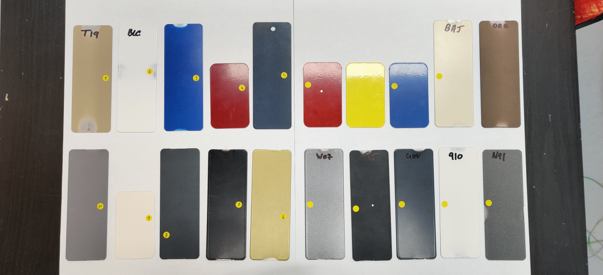
The metrological performance of Enovasense technology on thermolaquage (polymerized powder paint) has been validated through a rigorous independent study. The study followed the Measurement System Analysis (MSA) protocol of the Chrysler / Ford / General Motors Supplier Quality group, applied to 20 powder-coated aluminum samples spanning a representative range of industrial colors (white, black, gray, blue, red, yellow, gold, beige, brown).
Repeatability and reproducibility (R&R)
Three operators each measured 10 samples three times in conditions of repeatability and reproducibility. The combined R&R figure — the percentage of total measurement variation attributable to the measurement system rather than true part variation — is the key acceptance criterion: a R&R below 10% is considered excellent for production control purposes.
Accuracy across colors
The accuracy study compared Enovasense measurements against the eddy current reference using the normalised deviation En method, drawn from the Renault Group Central Metrology Laboratory standard. The test is passed when En < 1. All 20 samples — spanning colors including white, black, gray, gold, beige, blue, red, yellow, and brown — achieved a final favorable judgment. Three cases where the initial En slightly exceeded 1 were confirmed as satisfactory through a supplementary cross-section analysis (PaintBorer destructive measurement), which itself confirmed the Enovasense readings.
A key practical advantage of the Enovasense technology at the cured state is that a single calibration covers all powder paint colors on a given substrate. This means hundreds of production colors can be measured without any recalibration between color changes, a major operational advantage on lines producing multiple references.
06 — Industrial Integration
How to integrate Enovasense sensors: the HSR platform
For automated in-line powder coating control, Enovasense offers the HSR platform — a fully self-contained, turnkey measurement station designed for installation alongside a coating conveyor line, with no external controller, power station, or water cooling required.
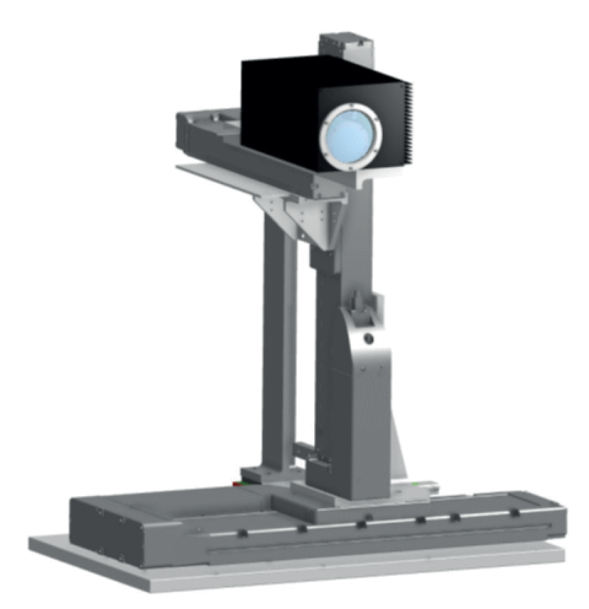
System architecture
The HSR system consists of a compact sensor head (272 × 160 × 129 mm, 4.3 kg) mounted on a 3-axis motorized gantry — a following axis (up to 2 500 mm stroke), a distance axis (300 mm), and a height axis (up to 2 000 mm). A tracking module using a structured laser line and camera continuously detects the position, shape, and distance of parts moving on the conveyor. An embedded controller runs the part detection and measurement sequence automatically, with no operator intervention required.
The system adapts automatically to variable part geometries: a software layer determines measurement positions within a predefined grid, automatically avoiding holes and part-free zones on the frame.
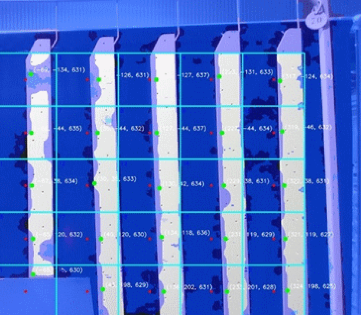
This is essential in architectural extrusion or fabrication contexts, where frames of 2 500 × 2 000 mm may carry dozens of parts with varying shapes and sizes in each production run.
Cycle time and coverage
For a typical application with 6 measurement points per frame and a static frame configuration, the total measurement cycle time is approximately 45 seconds: 15 s for frame positioning and stabilisation, 5 s for measurement point detection, 3 s for first-point approach, 2 s for the first measurement, and approximately 20 s for the approach and measurement of points 2 to 6. The system can immediately begin the next measurement sequence with no dead time between frames, ensuring high production coverage.
Data and supervision
All measurement results and system parameters are stored on-board and are accessible via a touchscreen HMI or keyboard. Data are streamed live to the plant network via an Ethernet RJ45 TCP/IP connection, enabling integration with MES, SPC systems, or line supervision software. A reference sample niche — accessible automatically by the sensor — allows periodic calibration verification against customer-supplied reference plaques without interrupting production.
Technical specifications — Enovasense HSR
Deployment steps
Site preparation
Client provides a 230 V / 16 A power outlet and an Ethernet network point at the machine footprint location. No compressed air or water cooling required.
Design & engineering phase
Enovasense delivers mechanical implantation plans, electrical schematics, safety risk analysis (EN 13849-1), and functional description within 4 weeks of order.
Factory acceptance test
Reduced functional test performed at Enovasense premises before delivery to validate conformity of all HSR functions against specification.
Installation, commissioning & training
On-site installation and set-up of the full machine, followed by Expert, Operator, and Maintenance training sessions delivered on-site. Full documentation (CE certificate, user manuals, electrical and mechanical drawings) provided.
12-month warranty & ongoing support
Full machine warranty for 12 months after provisional acceptance, with 1-week intervention commitment. Optional annual maintenance contract covering hotline, preventive maintenance visit, and software updates.
References
| Réference | Name | Status / Price | Datasheet |
|---|---|---|---|
| ARTICLE POWDER COATING | Non-Contact Thickness Measurement Of Powder Coatings |
Available
On quotation |
English |
| APPLICATION NOTE POWDER COATINGS | Controlling The Thickness of Powder Coatings In-Line |
Available
On quotation |
English |
Documents
| Type | Name | Download |
|---|---|---|
| Application | Epoxy and polyester powder paint thickness measurement | English French |
| Application | CONTROLLING THE THICKNESS OF POWDER COATINGS IN-LINE | French English |
