Applications / non-contact thickness measurement of zinc-flake coatings on brake discs
01 — Introduction
Zinc-flake coatings: the dominant anti-corrosion solution for automotive brake discs
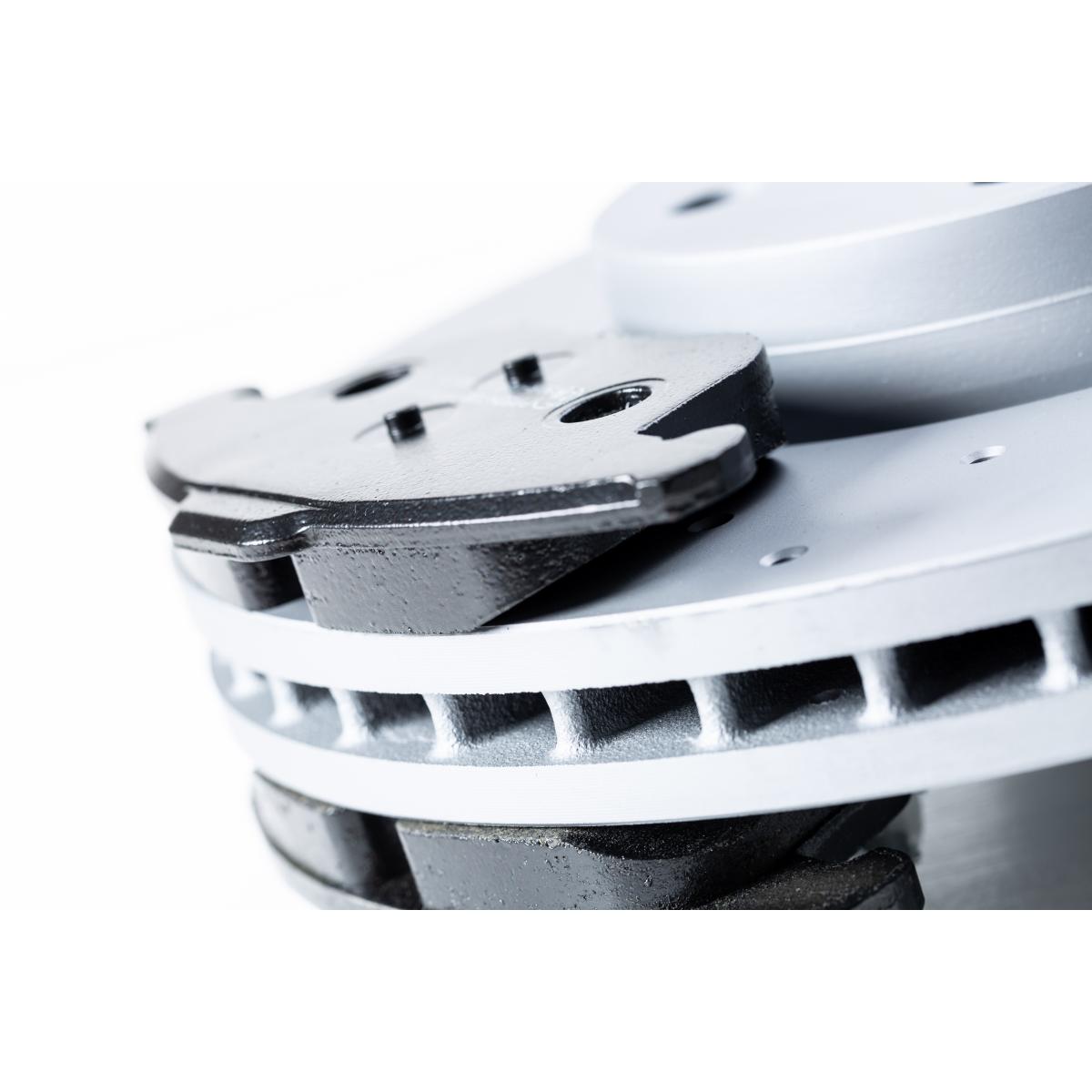
Since the early 2000s, zinc-flake coatings have become the dominant anti-corrosion solution for automotive brake discs. Brake discs are exposed to aggressive environmental conditions — humidity, saline fog, de-icing salts and temperature cycling — that can lead to corrosion and deterioration of the disc, both from an aesthetic and a functional point of view. The zinc-flake coating protects the non-friction areas of the disc: the hat, the venting channels and the edges that remain visible through modern open-design alloy wheels.
As a result, accurately measuring the coating thickness has become a key challenge for the automotive industry: enough zinc to guarantee the specified corrosion protection, but no more than necessary, in order to control process costs. Zinc-flake coating systems are supplied by well-established manufacturers of the automotive industry such as NOF Metal Coatings, Dörken, Magni and Wörwag.
The coating is typically sprayed onto the brake-disc surface before being baked in an oven, where the inorganic binder cross-links and consolidates the layer. As a non-electrolytic deposition method, it enables a controlled and uniform application even at low thicknesses — typically from a few micrometers to a few tens of micrometers — while avoiding hydrogen-embrittlement issues and providing consistent coverage of complex geometries.
Figure 1 — Brake-disc zinc-flake coating production sequence
02 — Quality Requirements
Why zinc-flake coating thickness is a critical quality parameter
OEM (Original Equipment Manufacturer) specifications impose strict requirements on zinc-flake coating thickness, uniformity and corrosion resistance, validated through salt-spray endurance targets. A coating that is locally too thin fails the corrosion requirement; a coating that is globally too thick wastes expensive coating material on every one of the millions of discs produced each year. Reliable, repeatable thickness control is therefore the key to holding both ends of that equation.
Zinc-flake coating structure: lamellar by design
A zinc-flake coating is a layering of thin lamellar zinc particles dispersed in an inorganic binder. The random orientation and stacking of the flakes within the binder matrix produce a coating that is inherently inhomogeneous and non-isotropic — the very properties that give the coating its excellent barrier and sacrificial protection are also the properties that make its thickness difficult to measure.
Figure 2 — Cross-section schematic of a zinc-flake coating
Controlling the process at both ends: wet and cured
Because the coating is applied wet and consolidated in an oven, the ability to measure the layer before curing gives the process engineer a decisive advantage: an out-of-specification deposit can be detected and corrected before the disc enters the oven, instead of being scrapped after it. Measuring after curing then confirms the final conformity of the shipped part. A measurement technique able to operate identically on both states closes the loop on the whole deposition process.
|
Cg = 5.69
Type 1 MSA capability index measured on a representative brake-disc sample — more than 4× above the standard 1.33 acceptance threshold
|
P = 0.676
Bias P-value of the Type 1 study — the bias versus the reference is not statistically significant
|
|
2 states
The same sensor measures the coating before curing (wet) and after curing (baked)
|
100 %
Inline inspection coverage achievable — every disc, in real time, without contact
|
03 — Measurement Challenges
Why conventional methods struggle on zinc-flake coatings
The lamellar structure of zinc-flake coatings makes measuring their thickness a real challenge: they combine thin layers, rough surfaces, a non-isotropic microstructure, and strong industrial throughput constraints. As a result, many conventional thickness-measurement methods struggle to deliver repeatable and reproducible results on this coating family.
Eddy-current / magneto-inductive probes: structure-dependent and operator-dependent
Contact probes based on eddy-current or magneto-inductive principles respond to the electrical and magnetic behaviour of the coating–substrate stack. On a zinc-flake layer, that response is highly dependent on the local flake orientation and on the surface roughness under the probe tip. Repeatability and reproducibility are consequently often operator-dependent, and automating a consistent probe contact on the curved, ventilated geometry of a brake disc is mechanically complex — making reliable in-line integration difficult. Finally, contact probes are simply not usable on the wet, uncured layer.
X-ray fluorescence: a reference method confined to the laboratory
Elemental X-ray fluorescence (Zn signal) is commonly used as a non-destructive reference technique. However, it requires radioprotection measures, is limited to relatively small parts inside a shielded chamber, and involves comparatively long measurement times — typically tens of seconds per point — which restricts its use to laboratory audits rather than production control.
The case for an integrated physical response
These limitations highlight the need for measurement approaches based on an integrated physical response of the coating–substrate system — a signal that averages over the flake microstructure rather than being scattered by it. The Enovasense approach relies on the integrated thermal response of the coating–substrate system, making the measurement much less sensitive to local microstructural variations while remaining fully compatible with industrial automation:
- Non-contact and non-destructive — no probe wear, no marking of the wet or cured layer.
- Both coating states measurable — the deposit can be verified before the oven and confirmed after it.
- Insensitive to operator influence — the laser spot replaces the probe tip; repeatability no longer depends on contact pressure or angle.
- Ready for automation — a compact optical head that a robot can carry to any point of the disc, or that the line can pass parts under.
04 — Technology Comparison
Why laser photothermal radiometry is the ideal solution
Enovasense’s patented laser photothermal radiometry resolves the limitations described above in a single sensor. A modulated laser beam generates a thermal wave inside the coating; an infrared detector captures the temporal profile of the heat that diffuses back to the surface; the coating thickness is extracted from the characteristic time of that thermal response. Because the thermal wave propagates through the full depth of the layer, the measurement integrates the lamellar microstructure instead of being scattered by it — and it works identically on the wet and on the baked coating.
| Criteria | Enovasense laser photothermal | Eddy current / magneto-inductive | X-ray fluorescence (XRF) |
|---|---|---|---|
| Measurement principle | Thermal diffusion response of the coating–substrate system | Electrical conductivity / lift-off response | Elemental X-ray fluorescence (Zn signal) |
| Non-destructive | Yes | Yes | Yes |
| Sensitivity to lamellar microstructure | Low to moderate | High — flake-orientation dependent | Moderate |
| Sensitivity to surface roughness | Low | High | High |
| Measurement of thin coatings (few µm) | Well suited | Challenging | Possible — but noisy |
| Repeatability / reproducibility | High | Operator- and calibration-dependent | Geometry- and setup-dependent |
| Measurement before curing | Yes — wet / uncured layer measurable | No — not suitable | No — not suitable |
| Automation / inline integration | Well suited | Difficult | Not suitable |
| Measurement velocity | High | High | Low — typically ~30 s per point |
| Radioprotection constraints | None | None | Required — X-ray source |
05 — Metrological Performance
Validated on real production samples from automotive suppliers
Enovasense technology has proven itself on real samples from automotive-industry suppliers. To assess the accuracy of the measurement, tests were performed on samples covering the whole thickness range of the tolerance interval. The Enovasense values were compared with microscopic cross-section measurements, considered here as the destructive reference method — and this intercomparison was carried out on both coating states: before curing and after curing.
Accuracy: intercomparison with the destructive reference
Figure 3 — Intercomparison: Enovasense vs microscopic cross-section (before and after curing)
Samples covering the tolerance interval, measured before curing (left) and after curing (right) and compared point-by-point with the destructive cross-section reference. Dashed line: 1:1 agreement. Solid line: linear regression.
There is a strong correlation between the values obtained by microscopic sectioning and those obtained with the Enovasense sensor — R² = 99.6 % before curing and R² = 99.4 % after curing on this sample set. It is also worth noting the method’s ability to accurately measure the thickness before curing, where the values consistently sit slightly above the final cured thickness, reflecting the consolidation of the layer in the oven — a capability that no contact-based method can offer.
Capability: Type 1 Measurement System Analysis
To further assess the intrinsic performance of the measurement system, a Type 1 Measurement System Analysis (MSA) was conducted on a representative brake-disc sample under controlled conditions: repeated measurements at the same point, compared against the reference value and the allocated tolerance.
Figure 4 — Type 1 MSA: run chart of repeated measurements at the same point
Run chart shown on the ±10 % tolerance-zone scale used by the Type 1 gage study; the point dispersion is drawn to scale with the measured capability indices (Cg = 5.69, Cgk = 5.67).
- Bias — the P-value (0.676) is higher than the standard alpha level of 0.05: the bias is not statistically significant. The measurement system is accurate relative to the reference.
- Capability — both Cg (5.69) and Cgk (5.67) exceed the standard threshold of 1.33: the measurement system is capable. Its variation is very small compared to the allocated tolerance — leaving ample resolution to detect genuine process drifts.
06 — Industrial Integration
How the Enovasense sensors integrate for brake-disc measurement
The same Enovasense sensor can be deployed at three levels, from laboratory qualification to 100 % in-line production control. The integration level is chosen according to the geometry of the measurement positions and the throughput of the line.
| Criteria | HKL2 control station | HKL-R control station | Inline integration |
|---|---|---|---|
| Motion system | 3-axis Cartesian system | 6-axis robotic arm | 6-axis robot / line-specific kinematics |
| Accessible geometries | Top & flat surfaces of the disc | Fillets, curved surfaces, side features | Defined by the line layout |
| Typical use | Laboratory / at-line thickness mapping | Automated mapping of complex 3D geometries | 100% real-time production monitoring |
| Measurement states | Before and after curing | Before and after curing | Before and/or after curing |
The HKL2 control station
The HKL2 performs thickness mapping through programmed cycles of movements and measurements, automatically covering the required positions on the part with a 3-axis Cartesian system. It is the natural tool for laboratory qualification, incoming inspection and at-line audits.
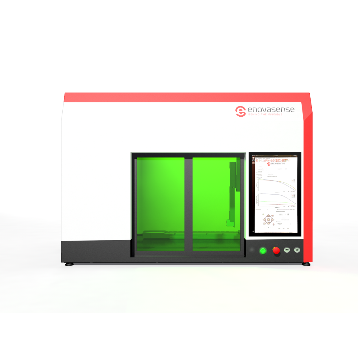
The Enovasense HKL2 control station — automated 3-axis thickness mapping
The HKL-R control station
The HKL-R performs automated thickness mapping through programmed motion and measurement cycles using a 6-axis robotic system, enabling access to complex geometries such as fillets, curved surfaces and side features that cannot be reached with conventional 3-axis systems — exactly the geometries found on a ventilated brake disc.
Video — The Enovasense HKL-R control station measuring brake discs
Automated 6-axis mapping of the zinc-flake coating thickness on a brake disc — the HKL-R full cycle.
Inline integration
The Enovasense measurement solution can also be integrated directly in-line, giving real-time monitoring of the zinc-flake deposition on 100 % of production. Carried by a six-axis robot, the sensor reaches fillets, curved surfaces and side features at line speed, and streams the thickness data to the plant supervision for closed-loop process control.
Deployment steps
| 1 | Application feasibility study Your coated discs are measured at Enovasense on both coating states; the calibration is established against your cross-section reference over your tolerance interval. |
| 2 | System definition Selection of the integration level (HKL2, HKL-R or inline), definition of the measurement positions, cycle time and part-specific tooling. |
| 3 | Factory acceptance test (FAT) Complete functional validation at Enovasense premises with your parts: accuracy vs reference, repeatability, capability and cycle time. |
| 4 | Installation, commissioning & training On-site installation and Site Acceptance Test, followed by operator and maintenance training with complete documentation. |
| 5 | Warranty & ongoing support 12-month warranty after acceptance, with optional annual maintenance contract covering hotline, preventive visits and re-calibration. |