Applications / measuring the thickness of bore-spray coating in-line
01 — Introduction
Bore-spray coating: a breakthrough for lighter, more efficient combustion engines
Bore-spray coating is a technology now deployed on a growing share of modern combustion engines. Instead of machining cylinders from a monolithic cast-iron block, engine manufacturers cast the block in aluminium and then deposit a thin iron or steel coating on the inner wall of each cylinder. The result is an engine that is dramatically lighter — a key lever for fuel economy and CO2 compliance — while keeping the tribological and hardness properties of iron where they matter most: at the piston–liner contact.
Four thermal spray processes are industrially used to deposit the inner coating, each with its own metallurgical signature and its own sensitivity to process drift:
Powder plasma Wire plasma Twin-wire arc (TWA) Flame spray & HVOF
In powder plasma and wire plasma processes, a plasma torch is generated inside the bore and iron powder or wire is projected into it. Twin-wire arc spraying strikes an electric arc between two iron wires fed into the bore. Flame spray and HVOF (High-Velocity Oxy-Fuel) rely on a combustion flame to accelerate iron particles towards the cylinder wall at very high velocity. After deposition, each block goes through a fine boring and honing sequence that removes the excess material and achieves the final bore diameter with the low surface roughness required for piston-ring sealing.
Figure 1 — Cylinder coating production sequence
02 — Quality Requirements
Why remaining coating thickness is the critical quality parameter
Once the coating has been deposited and the bore has been machined, the remaining iron thickness on the cylinder wall becomes the single most important quality indicator of the entire process chain. Two independent phenomena converge to make this measurement essential — and both are revealed specifically after the boring and honing steps, with honing being the most critical for thickness errors.
Boring centring error: asymmetric thinning of the wall
The fine boring operation that follows deposition must be perfectly concentric with the sprayed layer. In practice, centring is difficult to control with the micrometric precision required, and any eccentricity between the boring tool axis and the true centre of the coated bore directly translates into asymmetric material removal — a thicker wall on one side of the cylinder and a thinner wall on the opposite side. If the thin side falls below the design minimum, the cylinder is scrap.
 |
||
|
Possible thickness problem |
||
| Before boring | Wrong boring centering | Right boring centering |
Aluminium substrate roughness and threading
Before iron spraying, the raw aluminium bore is mechanically roughened — typically by fine threading or mechanical interlocking processes — to guarantee mechanical anchoring of the coating. This pre-treatment leaves a deep, irregular surface topography on the aluminium. The coating fills this topography and then the boring and honing tools re-establish a smooth cylindrical surface. The consequence is that the remaining iron thickness varies from point to point following the substrate micro-profile, and only a dense, angular-resolved thickness map can guarantee that a minimum coating is present everywhere.
Process drift monitoring
Beyond individual-part conformity, several process parameters can drift over time and collectively affect thickness: spray-gun wear, plasma power fluctuation, powder or wire feed-rate variation, temperature drift inside the bore during deposition, boring-tool wear, honing-stone consumption. Measuring 100% of production — rather than a destructive sample once every 5,000 blocks — is the only way to detect such drifts before they generate large populations of non-conforming engines.
|
<1µm
Reproducibility achieved on sprayed iron coatings (depending on the optical system selected and the layer thickness)
|
12 points
Minimum per cylinder (typical) to guarantee full angular & vertical coverage of the bore
|
|
< 60 s
Full-block cycle time (4-cylinder block, dual-probe configuration)
|
100 %
Inspection coverage — every block, every cylinder, in-line
|
03 — Measurement Challenges
Why conventional methods cannot meet automotive requirements
The geometry and the throughput of an automotive cylinder line push conventional thickness-measurement techniques to their limits. Two methods have historically been used; each has structural limitations that prevent their use for 100% in-line control.
Cross-section microscopy: accurate but destructive
Metallographic cross-section followed by optical microscopy is the reference method for coating thickness. It is accurate, directly traceable, and accepted in all quality protocols. But it is also destructive: the block is physically cut. For a complete engine block with four cylinders and at least twelve angular positions per cylinder, the complete operation — cutting, polishing, mounting, microscope measurement — typically requires about 42 hours of operator work and a lead time of one week. As a consequence, automotive plants sample approximately 1 block out of every 5,000 produced — meaning that any drift of the spray, boring or honing process can go undetected for several thousand engines before being visible in the quality data.
Contact magneto-inductive probes
Non-destructive contact probes based on magneto-inductive principles give reasonable correlation with cross-section data on this ferromagnetic-on-aluminium stack and can therefore accelerate the measurement compared to metallography. However, they require the probe tip to be physically pressed against the inner wall of the bore. Automating a consistent, repeatable contact inside a narrow cylinder — at twelve angular positions and several heights — is mechanically complex, sensitive to probe wear, and sensitive to residual particulates inside the bore.
The case for non-contact, in-line, 100% inspection
Measuring non-destructively, without contact, and at every step of the process chain transforms the quality paradigm:
- The same block can be measured after boring and after honing — if a defect appears, the process engineer immediately knows which step is responsible.
- Closed-loop feedback becomes possible: drift is flagged after a handful of parts rather than thousands.
- Full angular and vertical mapping of every cylinder, not a statistical sample — the only way to catch a local thin spot generated by a boring-centring error.
- Zero operator time on routine measurement: the system handles loading, measuring, and unloading automatically.
Video — The Enovasense HKXL control station in operation
Block loading, automatic 3-axis scanning, rotating probe inside each cylinder and real-time thickness data — the HKXL full cycle.
04 — Technology Comparison
Why laser photothermal radiometry is the ideal solution
Enovasense’s patented laser photothermal radiometry resolves all of the limitations described above in a single sensor. A modulated laser beam generates a thermal wave inside the coating; an infrared detector captures the temporal profile of the heat that diffuses back to the surface; the coating thickness is extracted from the characteristic time of that thermal response. The method is fully non-contact, non-destructive, and works on both the bored and honed bore states.
Joint patent with Renault Group — EP3781902B1. The application of Enovasense laser photothermal radiometry to inner-cylinder coating measurement is protected by a common patent co-owned with the Renault Group, validating the relevance of this measurement principle for the automotive engine industry.
| Criteria | Enovasense laser photothermal | Contact magneto-inductive probe | Cross-section (destructive) |
|---|---|---|---|
| Non-contact measurement | Yes | No — probe contact required | No — part is destroyed |
| Non-destructive | Yes | Yes | No |
| In-line automation inside a narrow bore | Yes — compact rotating probe | Difficult — reliable contact hard to automate | No |
| 100% inspection coverage | Achievable | Sampling only | ≈ 1 in 5,000 blocks |
| Reproducibility (standard deviation) | ±0.74 µm (±0.32%) | ±2.41 µm (±1.04%) | Reference method |
| Correlation with destructive reference (R²) | 83.0% | 79.4% | Reference method |
| Full-block measurement time | ≈ 50 s | Minutes — manual repositioning | ≈ 42 h / 1 week lead time |
| Closed-loop process feedback | Yes — real-time data to MES | Limited | No |
Reproducibility and R² values from the joint Renault Group — Enovasense study (see section 05). Performance depends on the optical system selected and on the layer thickness.
05 — Metrological Performance
Independent Renault Group — Enovasense study
The performance of Enovasense laser photothermal radiometry on bore-spray iron coatings after the boring step has been validated through a comparative study conducted jointly with Renault Group. Three techniques were compared on the same samples: destructive cross-section microscopy (reference method), a contact magneto-inductive probe, and the Enovasense non-contact photothermal sensor. Measurements were performed on 2 engine blocks of 3 cylinders each, at 12 positions per cylinder — a total of 72 points compared against the destructive reference.
The reproducibility and accuracy figures reported below correspond to the measurement configuration used during the Renault study. Actual performance on a given application depends on the optical system selected (focal length, numerical aperture, laser parameters) and on the thickness range of the coating measured.
Accuracy: calibration regression vs the destructive reference
For each non-destructive technique, the raw sensor signal measured at every one of the 72 points is plotted against the true thickness obtained by destructive cross-section microscopy (lab reference). The black line in each chart is the linear regression model used to convert the raw signal into a thickness value. The coefficient of determination R² quantifies how closely the measurements follow the regression model — a value of 1.00 would indicate perfect agreement. The Enovasense sensor reaches R² = 83.0 %, slightly above the contact probe (R² = 79.4 %), with a visibly tighter scatter around the fit.
Figure 2 — Calibration regression: lab-reference thickness vs raw sensor signal
Source: joint Enovasense–Renault Group study. 2 engine blocks × 3 cylinders × 12 positions = 72 measurement points. Each non-destructive technique’s raw signal is plotted against the lab reference thickness obtained by destructive cross-section microscopy.
Both non-destructive methods deliver a similar accuracy level against the destructive reference, confirming that the Enovasense technology is a credible alternative to the contact probe for this application — with a slightly tighter scatter around the regression model.
Reproducibility: a decisive advantage for Enovasense
The second part of the study evaluated reproducibility — the dispersion of 10 successive measurements taken at exactly the same point, expressed as a standard deviation. This is the metric that determines whether small process drifts can actually be resolved by the measurement system. The lower the standard deviation, the finer the drift that can be reliably detected.
Figure 3 — Reproducibility (standard deviation on 10 measurements at the same point)
Reproducibility values measured in the Renault Group study. Enovasense achieves a standard deviation more than 3× smaller than the contact probe.
With a standard deviation of ±0.74 µm (±0.32%), the Enovasense sensor delivers a reproducibility more than three times better than the contact probe (±2.41 µm / ±1.04%) on this bored iron coating. This margin is decisive for process-control use cases: it allows the detection of boring-centring errors, tool wear and spray-process drifts that would be buried inside the measurement noise of the contact probe.
Measurement at the as-sprayed state (secondary capability)
While the primary use case — and the focus of the Renault Group study — is the measurement of the coating after boring, and through the honing step which is the most critical for thickness errors, the Enovasense technology is also able to measure the coating directly after the spray deposition step, on the raw unmachined surface. This secondary capability enables process engineers to separate the contribution of the spray step from the contribution of the machining steps when investigating a non-conformity, and to accelerate the qualification of new spray recipes. A dedicated calibration is used for this state, distinct from the one used on the bored and honed surfaces.
06 — Industrial Integration
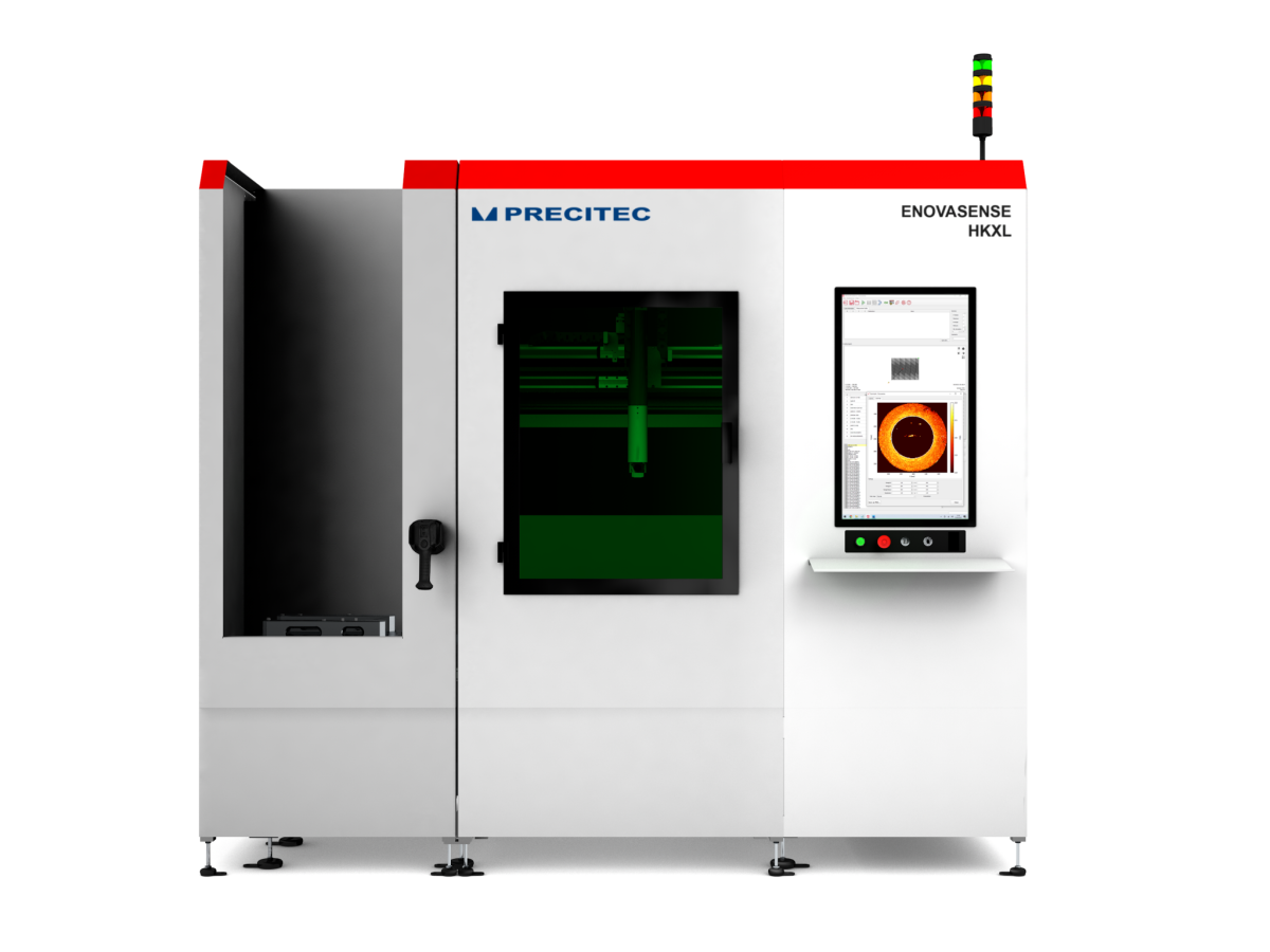
The HKXL platform: a turnkey 100% control station
For 100% in-line coating thickness control on cylinder block production, Enovasense offers the HKXL platform — a fully self-contained, turnkey measurement station designed to be installed directly alongside the machining line. The HKXL handles automatic loading, multi-cylinder measurement, calibration, and data export, with no operator interaction during the measurement cycle.
System architecture: three independent structures
The HKXL is built as three mechanically decoupled structures so that any vibration or shock generated during block loading cannot propagate to the measurement probe and bias the reading:
Figure 4 — HKXL system architecture
The Enovasense probe
At the heart of the system is a compact probe designed to enter each cylinder bore. The probe is introduced from above; its lower section rotates to scan the full 360° of the bore, and the height axis addresses several vertical positions. Air is continuously blown on the exit lens to prevent contamination from coating dust, oil mist, or chips. The standard probe diameter is 66 mm, compatible with most cylinder diameters; the focal length of the exit lens can be adapted to other bore diameters on request. Multi-probe configurations — typically two probes operating in parallel on two cylinders at once — are available to shorten the per-block cycle time.
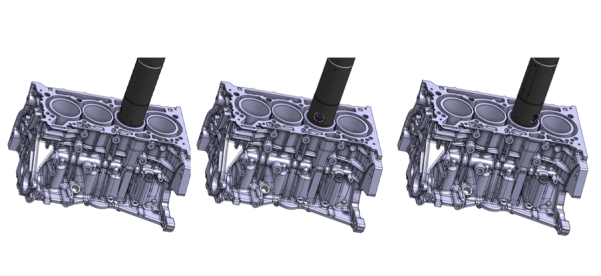
Automated rotation of the lower section of the Enovasense probe for scanning various angles within each cylinder bore
Cycle and throughput
For a 4-cylinder block measured with 12 points per cylinder in a dual-probe configuration, the full measurement cycle takes approximately 50 seconds, including automatic block loading, 3-axis positioning, probe insertion, 360° scanning, probe retraction, data display on the HMI, CSV export, and unloading. Several operating modes — Standard automated, New-part creation, Free, Maintenance — cover production, recipe creation, qualification and service intervention. A reference calibration sample is stored in a dedicated niche inside the machine and measured periodically to verify that the sensor has not drifted.
Data, traceability and MES integration
All thickness results are stored on-board (time-stamped) and visualised on a 27-inch touchscreen HMI. A CSV export is generated at the end of each cycle and data are streamed in real time to the plant network via Ethernet (TCP/IP), enabling integration with the customer MES, SPC, or supervision systems. Each measurement is traced with its operator badge ID, part ID, part reference, and the calibration curve used — providing full traceability on every block that leaves the line.
Technical specifications — Enovasense HKXL
| Overall machine dimensions (L × W × H) | 2600 × 1300 × 2200 mm |
| Weight | ≈ 600 kg |
| Measurement area (XYZ) | 600 × 800 × 400 mm (adjustable) |
| Probe diameter (standard) | 66 mm — for Ø 72.2 mm cylinders |
| Probe rotation | 360° angular scan inside the bore |
| Laser wavelength / power | 980 nm / 10 W |
| Reproducibility | < 1 µm (depends on the optical system selected and the layer thickness) |
| Cycle time (4-cyl block, 2 probes, 12 pts/cyl) | ≈ 50 s |
| Electrical supply | 400 V — 50 Hz — ≈ 3 kVA |
| Pneumatic supply | > 5 bar, clean & dry |
| Data interface | Ethernet TCP/IP — CSV export — MES / SPC integration |
| Safety | Light curtain, coded magnetic door switches, 2 emergency stops, CE-compliant |
| Acoustic emission | < 70 dB(A) |
| Operating temperature | +5 °C to +50 °C |
Specifications are indicative and can be adapted to specific customer requirements.
Deployment steps

Documents
| Type | Name | Download |
|---|---|---|
| Certification | Application note : Thickness measurement of steel coating in aluminum engine cylinder block | English |
