Applications / inorganic coatings on aircraft engines
Thickness measurement of inorganic coatings for aircraft engines
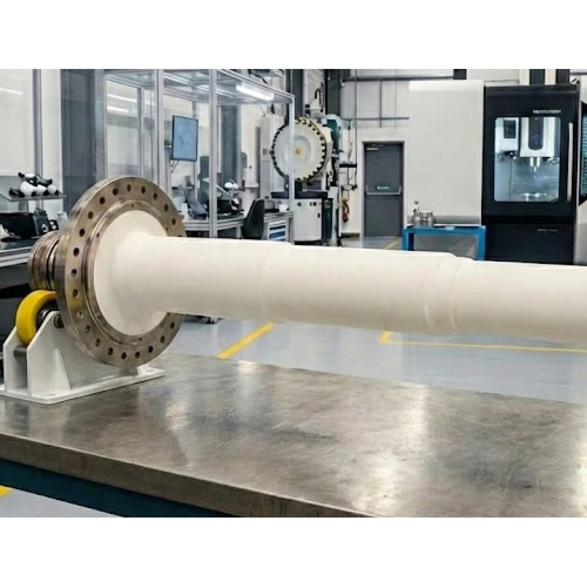
Fan shafts, turbine shafts, compressor blades, vanes, casings, fasteners are subject to extreme thermal and mechanical stress that create the conditions for dangerous forms of corrosion such as pitting or stress corrosion.
Inorganic coatings are used in such aircraft engines parts to create a highly resistant anticorrosion protection. They are generally composed of a metallic particle pigment (typically aluminum) that is suspended in an inorganic binder (chromate, silicate or phosphate). This creates a double effect of anticorrosion protection : as the aluminum particles play a sacrificial role in being corroded instead of the steel alloy substrate, the ceramic binder creates a barrier protection for the substrate and a seal protection for the aluminum particles. Those ceramic binders are resistant to temperatures of 600°C and remain strong face to typical thermal stresses.
Among the most known coatings used, one can count the Socoglaze coatings from Socomore, the Sermetel family from Linde AMT or the Ipcoat/Ipseal from Indestructible Paint.
Measuring the thickness of the coating within a complex process
Applicating such coatings is a complex process including steps of surface preparation, coating spraying, drying and curing, compaction and sometimes an additional topcoat spraying. It is a critical to achieve a very strict thickness range in order to ensure a minimum protection while avoiding the risks of overdeposition (delamination, crazing…).
Non-destructively controlling the thickness of those coating at the end of the full process is key to validate the performance of the coating, but it is also too late as the compacted coating would be very costly to remove in the event of a non-conformity on the thickness.
Enovasense has partnered with Safran Aircraft Engines within an R&D project monitored by M2P to develop and implement such a chrome VI-free coating, being REACH compliant and an environmentally friendly alternative to existing coatings with chromate binders. Within this project, Safran has validated the Enovasense coating thickness sensors on several TRL scale levels for measuring such inorganic coatings.
How the Enovasense technology is revolutionizing this measurement
The main advantages of the Enovasense technology in comparison to conventional magnetic technologies for measuring the thickness of such coatings are multiple :
| Criteria | Enovasense (Laser Photothermal) | Magnetic probes |
|---|---|---|
| Contact and distance | Non contact | Contact |
| Operator impact | Independent of operator | Operator dependent (how the contact is applied) |
| Calibration | No recalibration needed | Needs regular recalibration |
| Shape dependency | Calibration independent of the shape, curvature or geometry | Calibration is shape dependent |
| Edge effect | No edge effect | Not working close to edges and holes |
| Internal accessibility | The T060 probe can enter within the shaft and measure everywhere | Difficult to impossible to measure deep within shaft internal diameters |
| Coating state | Possible to measure before curing or compaction of the coating | Only measurable on the cured and compacted coating (contact could scratch coating in its intermediary state) |
| Automation | Can be automated by embedding the probe on a robotic arm | Difficult to automate the measurement due to the contact operation |
In other terms, the Enovasense technology is offering a breakthrough within such kind of processes by allowing the measurement with a high precision at the different steps of the coating process.
How Enovasense performs on such coatings
Regarding the accuracy of the measurement, Enovasense performed test on samples that showed various thickness levels covering the whole range of the tolerance interval. Those measurements were then compared with profilometric step height measurements.
Whereas the profilometric value gives a unique value localized on 1 line, Enovasense was able to perform several readings on various locations of the sample. The measurement time of Enovasense is indeed only of 1 second per measured point.
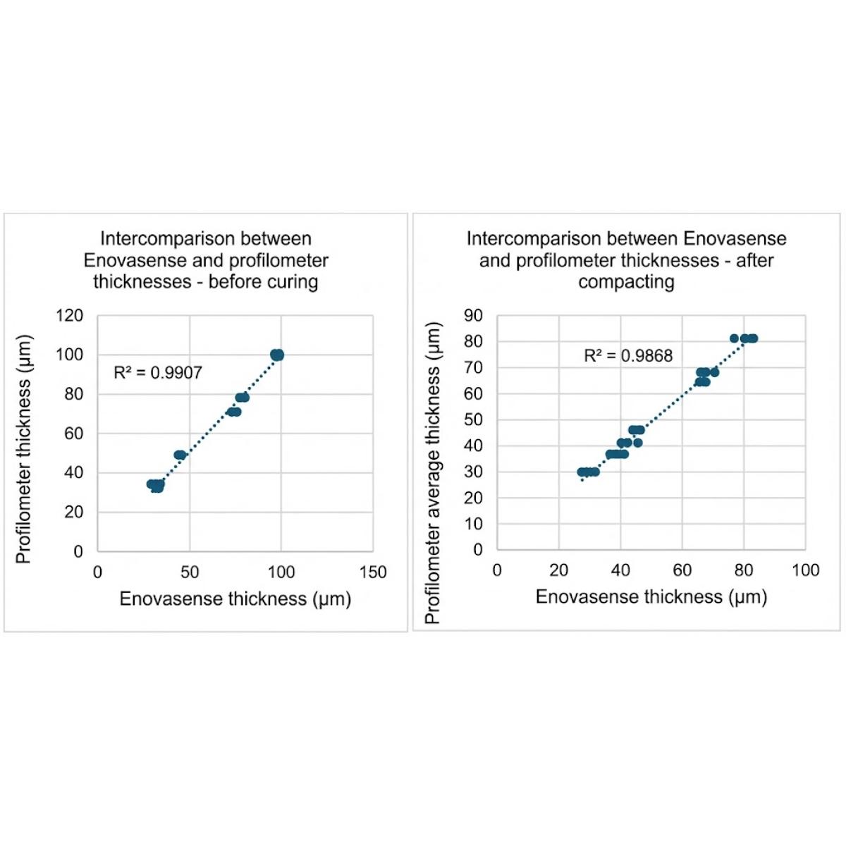
We observe that whatever the step of the process where the samples are measured – either before curing or after compacting – the Enovasense measurement highly correlates with the profilometer values.
We then performed a type 1 MSA study on a sample of 41µm, quite in the middle of the range of interest.
The trademarks mentioned in this article belong to their respective owners. Enovasense is not affiliated with any of these entities. They are mentioned for informational purposes only.
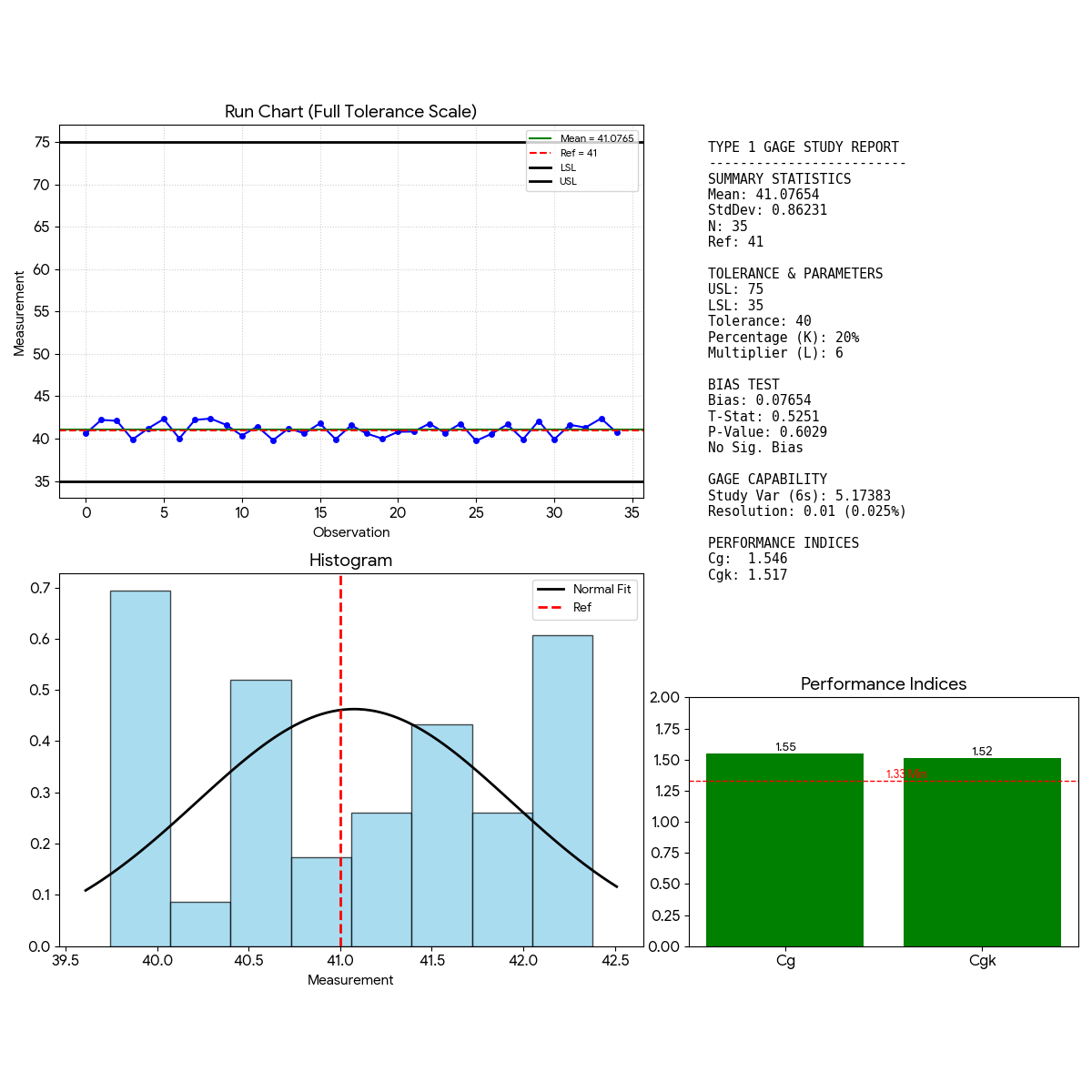
- Bias: The P-Value (0.603) is higher than the standard alpha level of 0.05. Therefore, the bias is not statistically significant. The measurement system is accurate relative to the reference.
- Capability : Both Cg (1.55) and Cgk (1.52) exceed the standard threshold of 1.33. This indicates that the measurement system is capable. The variation is acceptably small compared to the allocated tolerance.
Finally, for this application, the impact of the measurement distance and measurement angle was tested. We found that the sensor was able to stay within a +/-1µm range when varying the distance from 15 to 25µm (with a nominal distance at 20µm) as well as when varying the angle of approach from -40° to +40° (with a nominal angle at 0°).
How to integrate Enovasense sensors for controlling such coatings
The Enovasense probes are compact and lightweighted which allows to imagine various integration possibilities :
Robotic integration
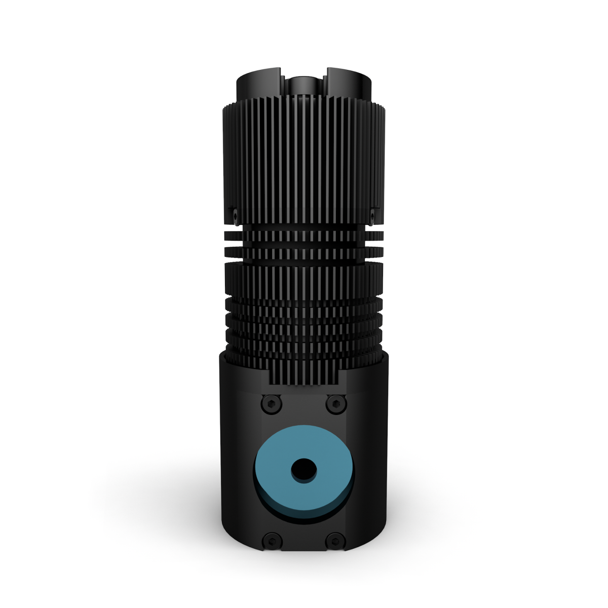
The T060 probe can be implemented on a robotic arm and then automatically control various positions of the part to measure. Together with the 90° optical tool, it can also be inserted inside a turbine shaft in order to inspect internal coated areas.
Offline control station
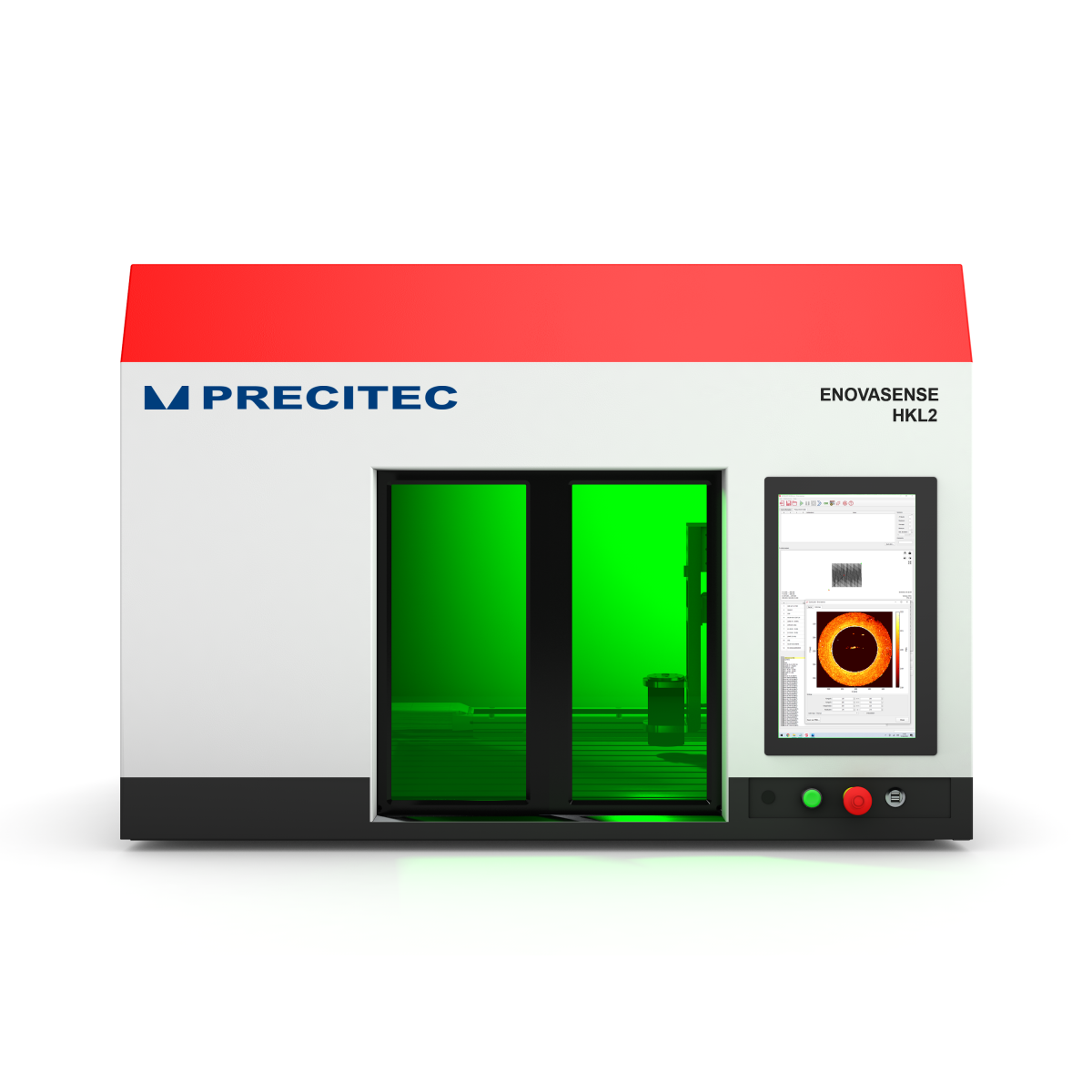
The HKL2 control station allows to perform thickness mapping and cycles of movements and measurements in order to automatically measure various positions on the part.
Manually positioned arm system
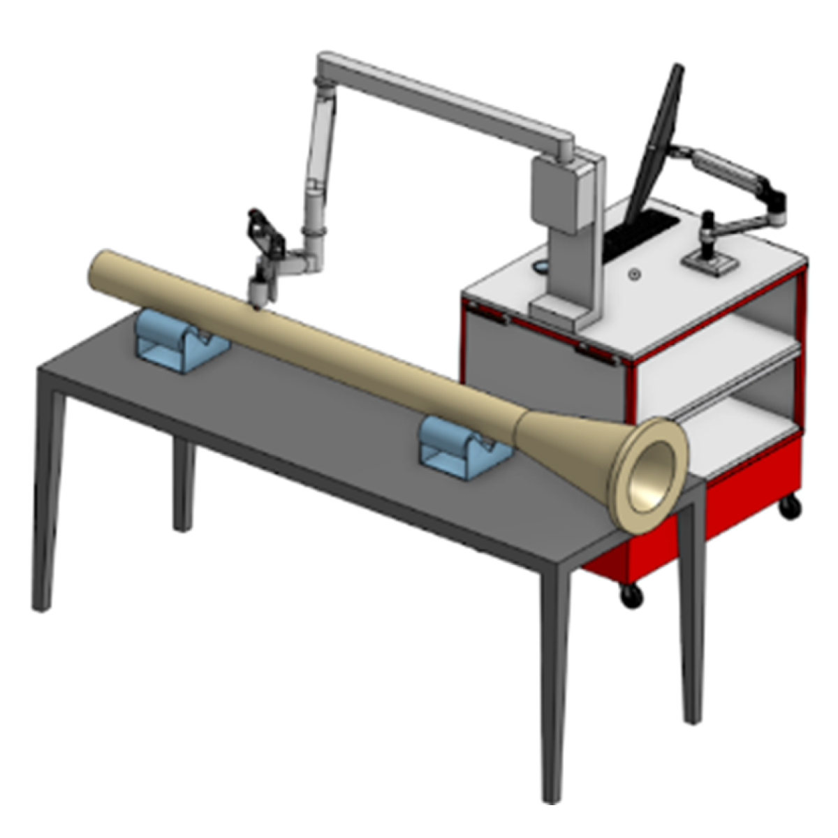
The Enovasense sensor can also be positioned on a self-supporting arm allowing a stable positioning of the sensor by the operator.