Applications / e-coat
01 — Introduction
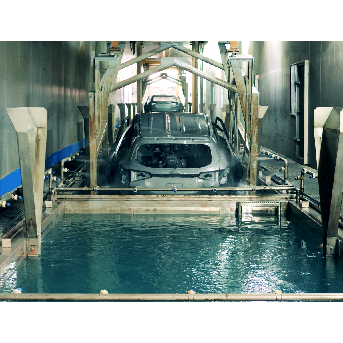
E-coat / KTL: a critical process for automotive corrosion protection
Electrophoretic coating — commonly known as E-coat, KTL (Kathodische Tauchlackierung) or cataphoresis — is a dip-coating process in which a conductive metal part is immersed in a water-based paint bath and coated under the action of an electric field, before being cured in an oven to form a uniform, dense and highly corrosion-resistant polymer film. With the rapid expansion of the electric-vehicle fleet and the steadily increasing demands on vehicle durability, E-coat has become one of the most strategic surface-treatment steps in the automotive industry.
Beyond automotive body-in-white and battery enclosures, E-coat is widely deployed across many industrial sectors — from electrical enclosures and switchgear to heavy industrial equipment, agricultural machinery, HVAC components and energy-related hardware. In all of these applications, E-coat stands out as one of the most efficient methods for protecting metal structures against corrosion, thanks to its excellent edge coverage, its ability to reach recessed geometries inaccessible to spray processes, and its outstanding adhesion to the substrate.
Automotive body-in-white Battery enclosures Chassis & suspension Electrical enclosures Industrial equipment HVAC & energy
A typical E-coat stack combines a phosphate (or zirconium-based) pre-treatment for adhesion and corrosion protection, followed by the electrophoretic layer itself, whose target dry film thickness usually ranges from 15 µm to 35 µm depending on the specification. On automotive body assemblies, the E-coat film is generally overlaid with a primer, basecoat and clearcoat system, but it is the E-coat layer that carries the corrosion-protection function over the vehicle lifetime.
02 — Quality Requirements
Why controlling E-coat thickness is essential
E-coat thickness is one of the most critical quality parameters of the entire automotive paint shop. Unlike decorative paint layers, the primary function of E-coat is protective, and deviations from the target thickness have direct consequences on corrosion performance, warranty exposure and material cost.
Too thin: corrosion failures and warranty risk
A film that is locally too thin will not deliver the corrosion-protection performance required by OEM specifications. Insufficient coverage on edges, weld seams or recessed areas is one of the main root-causes of premature corrosion perforation in service, generating costly warranty claims and potentially impacting brand reputation. For electric-vehicle battery enclosures in particular, local under-thickness can compromise the long-term integrity of safety-critical components.
Too thick: material waste and downstream defects
Conversely, over-thickness wastes expensive paint material on high-volume production lines, increases energy consumption during curing, and can generate cosmetic defects such as sagging, craters or surface roughness that propagate into the topcoat appearance. On complex assemblies with tight dimensional tolerances, excess thickness can also interfere with fit-and-finish.
Local homogeneity: the real quality challenge
Because E-coat deposition is driven by the local electric field, the key quality challenge is not simply to reach an average target thickness, but to guarantee sufficient local thickness homogeneity across the whole part — including edges, recesses and Faraday-cage-prone geometries. OEM specifications therefore impose strict requirements on minimum local thickness, uniformity, and corrosion resistance, which can only be validated through multi-point thickness mapping.
|
15–35 µm
Typical E-coat dry film thickness
on automotive components |
< 3%
Typical measurement precision
(% of measured value) |
|
± 6 mm
Stand-off tolerance
around nominal distance |
1 s
Measurement time
per point |
03 — Measurement Challenges
Why conventional measurement approaches fall short on E-coat
Electrophoretic deposition is driven by the locally applied electric field. This means that the deposit is intrinsically uneven — it tends to be thicker on edges and thinner in cavities or recessed areas. On top of this geometry-induced variability, E-coat layers are relatively thin (typically 15–35 µm) and are applied on complex, large, three-dimensional parts. These specificities create several fundamental challenges for quality control.
The limitations of contact techniques
The most common industrial approaches for E-coat thickness are eddy-current or magnetic-induction probes. Both are contact methods: the probe must physically touch the coating surface. Their response is highly sensitive to local geometry, surface curvature and substrate properties, which is a serious limitation on E-coated parts whose key failure-risk areas are precisely the edges and curved zones where these probes perform worst. Their repeatability is also operator-dependent, and they cannot be used before curing, since the uncured film is fragile.
The limitations of destructive cross-sections
Metallographic cross-sections are considered a reference method, but they are inherently destructive, slow (several hours per sample) and purely local — a few points per part at most. They are incompatible with any form of representative thickness assessment on a complete body-in-white or a large battery enclosure, and of course with any form of in-line monitoring.
The need for an integrated, non-contact response
To be relevant for E-coat, a measurement method must deliver an integrated physical response of the coating–substrate system — one that is not dominated by local geometric singularities, that can address thin films, and that can be automated in-line or on robotized cells for dense multi-point mapping.
04 — Technology Comparison
Why laser photothermal radiometry is the ideal solution for E-coat
Laser photothermal radiometry — the patented technology developed by Enovasense — resolves all of the limitations described above in a single, compact, integrable sensor. A modulated laser beam generates a controlled thermal wave inside the coating, and an infrared detector captures the resulting heat-diffusion signal; the coating thickness is extracted from the temporal profile of this thermal response. The method is fully non-contact, non-destructive, and naturally compatible with thin films, complex geometries and robotic integration.
"The Enovasense approach is based on the integrated physical response of the coating–substrate system, making it less sensitive to local geometrical singularities while remaining compatible with complex part geometries and industrial automation."
— Enovasense E-coat validation study| Criteria | Enovasense laser photothermal | Eddy current / Magnetic induction | Metallographic cross-section |
|---|---|---|---|
| Measurement principle | Thermal diffusion response — integrated physical signal | Electrical conductivity response | Direct local thickness observation |
| Non-contact measurement | Yes | No — probe contact required | No — part is destroyed |
| Non-destructive | Yes | Yes | No — destructive |
| Sensitivity to part geometry | Low — compatible with complex geometries | High — edges, curvature, accessibility | Low — but only at selected location |
| Spatial representativity | High — multi-point mapping | Very low — single local point | Very low — single local point |
| Thin coatings (0–10 µm) | Well suited | Challenging — high noise | Possible but noisy |
| Suitability for large parts | Suitable | Suitable — manual only | Very limited |
| Measurement before curing | Possible | Not suitable | Not suitable |
| In-line / robotic integration | High — robot & gantry ready | Difficult | Not suitable |
| Measurement speed | ≈ 1 s per point — fully automated | High — but manual repositioning | Hours per sample |
05 — Metrological Performance
How Enovasense laser photothermal performs on E-coat
The performance of Enovasense technology on E-coat has been validated on real automotive components, covering the full thickness-tolerance interval. The study combined a reference sensor configuration, a point-by-point intercomparison along a variable-thickness line, a 20× repeatability assessment at three thickness levels, a Type 1 Measurement System Analysis (MSA) and a stand-off distance robustness test.
Sensor parameters for E-coat
The Enovasense sensor used for this study operates at a laser wavelength of 980 nm with a laser power of 1 W and a measurement time of 1 000 ms per point. The sensor-to-part nominal stand-off distance is 40 mm, and the laser spot diameter on the part surface is 2.3 mm. The sensor is non-radiative and fully compatible with industrial integration on robotized or conveyor-based stations.
Intercomparison along a variable-thickness line
An automated line scan was performed on a sample exhibiting a thickness gradient from approximately 15 µm to 23 µm, with one Enovasense measurement every 1 mm. Reference destructive measurements (metallographic cross-section) were performed at three selected positions along the same line. The Enovasense scan follows the thickness gradient with excellent fidelity and matches the reference points within their own measurement uncertainty.
Enovasense measurement every 1 mm along a line covering the full tolerance range. Three destructive cross-section references were taken along the same line for validation.
Correlation with the destructive reference
Plotting the Enovasense reading against the destructive reference value at the three validation points yields a linear fit with a slope very close to 1 and a residual offset well within the combined uncertainty of both methods. This demonstrates that the Enovasense laser photothermal technique is not only repeatable but also quantitatively accurate across the whole E-coat thickness tolerance range, with no need for a material-specific correction factor beyond the standard calibration.
Enovasense readings plotted against the destructive cross-section reference at three thickness levels covering the full tolerance range. The regression slope is 1.003 with R² = 0.999, confirming the absence of material-specific correction on E-coat.
20× repeatability at three thickness levels
Repeatability was assessed by repeating the Enovasense measurement 20 times at three representative positions of the same sample (thin, medium and thick), without moving the sensor. The RMS standard deviation remained well below 0.25 µm at all three thickness levels, which is below 1.4 % of the measured value in every case — a level of stability typical of a fully capable measurement system.
20 successive measurements without moving the sensor at each of the three positions. The standard deviation decreases at higher thickness, reflecting the better signal-to-noise ratio of the photothermal response on thicker layers.
Type 1 Measurement System Analysis
To further qualify the intrinsic performance of the measurement chain, a Type 1 MSA was carried out on a representative reference sample, repeating the Enovasense measurement 50 times under controlled conditions. The three standard outputs — run chart against the tolerance limits, distribution histogram, and capability indices — all confirm that the measurement system is capable for E-coat thickness control.
Run chart — 50 repeated measurements on the reference sample, plotted on the full tolerance scale
|
Distribution histogram (50 measurements) |
Capability indices Cg (capability) 1.58
0↑ 1.33 threshold2.0
Cgk (centering) 1.54
0↑ 1.33 threshold2.0
Bias P-value 0.847
↑ 0.051.0
✓ Measurement system capable. Both Cg and Cgk exceed the 1.33 threshold. Bias is not statistically significant (P > 0.05). |
Type 1 MSA conducted on a single reference sample of nominal thickness 18.5 µm, specification ±3 µm, 50 successive Enovasense measurements under controlled conditions.
Robustness to stand-off distance variation
An important criterion for industrial integration is the sensitivity of the measurement to stand-off distance variations, which inevitably occur when a sensor is mounted on a robot arm or gantry and faces parts with a non-negligible shape dispersion. To quantify this sensitivity, the same variable-thickness line was re-measured at seven stand-off distances ranging from 32 mm to 44 mm around the nominal 40 mm working point. For each distance, the average deviation on the whole line, compared to the nominal 40 mm measurement, was computed.
The figure below shows the resulting deviations plotted on a ± 2 µm scale — which is already a small fraction of the E-coat thickness itself. All deviations barely leave the zero line, which is a direct visual demonstration of how negligible the stand-off influence is on the measurement over a ± 6 mm working window.
All deviations remain within ± 0.2 µm over a ± 6 mm stand-off window — a negligible fraction of the ± 2 µm scale shown. This very large mechanical tolerance is a decisive advantage for robot or gantry integration in industrial environments.
06 — Industrial Integration
Two integration architectures for E-coat thickness control
The robustness of the Enovasense photothermal measurement to stand-off distance variations — less than 0.2 µm deviation over a ± 6 mm window — enables two complementary integration architectures, selected according to the part geometry, the production volume, and the conveyor strategy of the paint shop.
|
Option A Robot-handled part in front of fixed sensor(s)The part is gripped by a robotic arm — typically the same cell that handles loading and unloading on the paint line — and presented successively in front of one or several fixed Enovasense measurement heads. Each sensor is mounted on a mechanical support at the nominal 40 mm stand-off distance, looking at a predefined measurement point on the part trajectory. Best suited to:
Key benefits:
|
Option B HSR platform — sensor head moved over a conveyed partFor large parts transported on a conveyor — full body-in-white, large battery enclosures, architectural sub-assemblies — Enovasense offers the HSR platform, a fully self-contained, turnkey measurement station. The sensor head (272 × 160 × 129 mm, 4.3 kg) is mounted on a 3-axis motorized gantry that tracks the part as it moves on the conveyor. Best suited to:
Key benefits:
|
Technical specifications — Enovasense HSR
Deployment steps
Site preparation
Client provides a 230 V / 16 A power outlet and an Ethernet network point at the machine footprint location. No compressed air or water cooling required.
Design & engineering phase
Enovasense delivers mechanical implantation plans, electrical schematics, safety risk analysis (EN 13849-1) and functional description within 4 weeks of order.
Factory acceptance test
Reduced functional test performed at Enovasense premises before delivery to validate conformity of all functions against specification.
Installation, commissioning & training
On-site installation and set-up of the full system, followed by Expert, Operator and Maintenance training sessions. Full documentation (CE certificate, user manuals, electrical and mechanical drawings) provided.
12-month warranty & ongoing support
Full machine warranty for 12 months after provisional acceptance, with 1-week intervention commitment. Optional annual maintenance contract covering hotline, preventive maintenance visit and software updates.