Applications / non-contact laser cladding coating thickness measurement on brake discs
Thickness monitoring of laser cladding coatings on brake discs
Automotive manufacturers face a crucial challenge since the adoption of the Euro 7 standard in 2024. This standard aims to reduce non-exhaust particulate emissions, which are largely caused by brake disc wear. As a result, laser cladding is emerging as a key enabling technology that can significantly reduce emissions related to brake discs.
Brake disc laser cladding quality control is essential in the automotive industry
Brake discs are exposed to severe operating conditions such as high mechanical loads, elevated temperatures and repeated thermal cycles, which can lead to wear and degradation of the friction surface, both from a functional and durability point of view. Thus, the laser cladded layer applied to the brake disc protects the friction surface by improving wear resistance and extending component lifetime.
As a result, OEM (Original Equipment Manufacturer) specifications impose strict requirements on laser cladded layer thickness and uniformity, making reliable and repeatable control of laser cladding on brake discs essential.
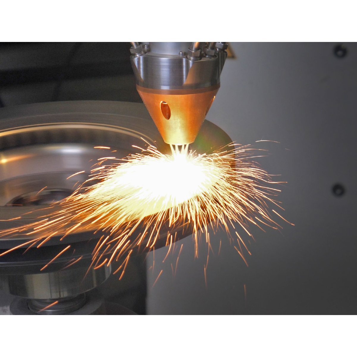
Laser cladding process
Laser cladding is a surface treatment process that uses a high-energy laser to create a small melting pool on the surface of a substrate onto which powder or wire is sprayed, A dense coating is then formed, metallurgically bonded to the substrate. It is therefore necessary to check the surface condition to ensure that the coating layer is uniform across the entire brake disc. However, the thermal gradient and tolerances inherent in the use of laser cladding make standard thickness measurement methods difficult to apply on an industrial scale.
Why laser cladding layer thickness is difficult to measure
Measuring the thickness of a laser cladding layer is a real challenge, as the process produces a rough surface consisting of overlapping beads with local variations in thickness due to the dynamics of the molten pool. Additionnally, the presence of carbide particles aiming at increasing the resistance of the layer disturbs numerous measurement principles. As a result, many conventional thickness measurement methods struggle to deliver repeatable and reproducible results.
Technical Challenges in Laser cladding layer Thickness Measurement
| Criteria | Height sensor / laser triangulation | Metallo-graphic cross-section | Enovasense photothermal |
|---|---|---|---|
| Measurement principle | Measurement of surface topography before and after deposition | Direct local thickness observation | Thermal diffusion response |
| Destructive / non-destructive | Non-destructive | Destructive | Non-destructive |
| Sensitivity to part geometry | High (edges, curvature, accessibility) | Low (selected measurement location) | Low to moderate, compatible with complex geometries |
| Measurement of thin coatings (few µm) | No | Possible but noisy | Well suited |
| Suitability for total thickness measurement after 2 layers deposition | Risk of loosing the reference measurement | Suitable | Suitable |
| Automation / inline integration | Difficult | Not suitable | High (robot integration, thickness mapping) |
| Measurement velocity | High | Extremely low | High |
Conventional industrial approaches for measuring Laser cladding layer thickness, such as metallographic cross-sections and Height sensor / laser triangulation, present significant technical limitations. Destructive cross-sectioning, while considered a reference method, is inherently local, time-consuming and incompatible with representative thickness assessment on large or complex parts. As for distance-based measurement methods such as laser triangulation, their accuracy is highly dependent on the surface geometry, roughness and local orientation. Furthermore, the use of a surface reference point makes these methods poorly suited to multi-layer production processes, where the functional layer thickness cannot be reliably inferred from surface height alone.
Enovasense approach relies on an integrated thermal response of the coating–substrate system, making them less sensitive to local microstructural variations while remaining compatible with industrial automation.
Intercomparison thickness measurement of Laser cladding layer
Enovasense has partnered with Fritz Winter and Mercedes within an industrial validation project to develop and assess laser cladded brake disc solutions addressing current and upcoming automotive emission requirements. Within this project, Mercedes and Fritz Winter validated the Enovasense laser-based thickness measurement technology on laser cladded brake discs, across several industrial maturity levels, to monitor the cladded layer thickness in representative production conditions.
The following figure presents measurements performed on various samples. Three discs with thicknesses ranging from 200 to 350µm were measured, and their response was used to calibrate the Enovasense sensor. This calibration was then applied to measurements taken on validation samples (of unknown thickness), which were subsequently verified using micrographical cross-sections.
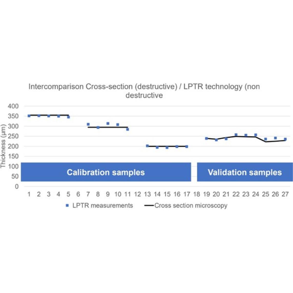
There is a strong correlation between the values obtained by microscopic sectioning and those obtained using the enovasense sensor.
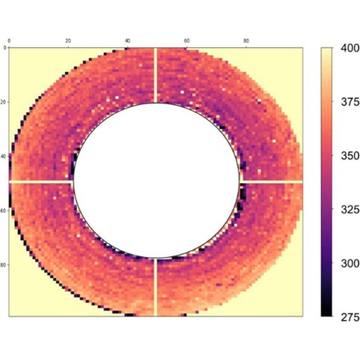
The integration of the enovasense method also allows for a complete scan of the surface treated with laser cladding in order to assess its uniformity :
How the Enovasense sensors can be integrated for brake discs measurement
The HKL2 control station
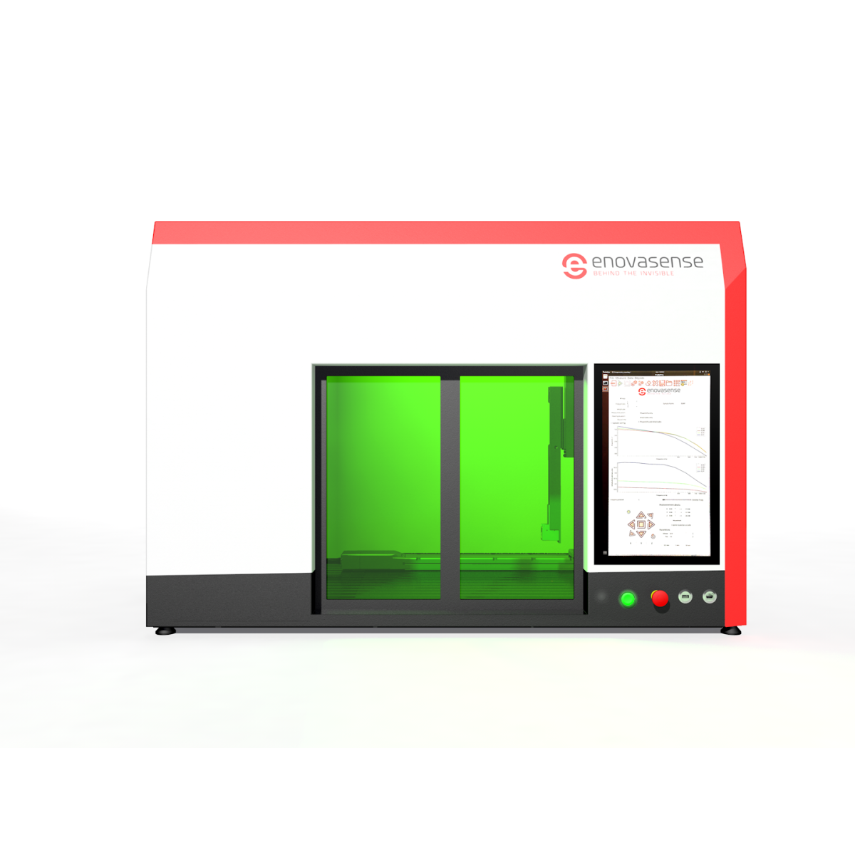
It allows to perform thickness mapping and cycles of movements and measurements in order to automatically measure various positions on the part with a 3D axis sytem.
The HKLR control station
It allows automated thickness mapping through programmed motion and measurement cycles using a 6-axis robotic system, enabling access to complex geometries such as fillets, curved surfaces, and side features that cannot be measured with conventional 3-axis systems.
Inline integration
The enovasense measurement solution can be integrated directly inline, following the laser cladding step.