Applications / non-contact thickness measurement of enamel coatings at every state of the process
01 — Introduction
Enamel coating: vitreous glass fused to metal and glass
Vitreous enamel — also called porcelain enamel — is a thin layer of glass fused onto a substrate at high temperature. A finely milled glass frit is applied as a wet slurry (slip), an electrostatic dry powder, or a screen-printed paste, dried, and then fired at roughly 800–900 °C, where it melts and bonds chemically to the part. The result is a hard, glossy, chemically inert surface that resists corrosion, abrasion, high temperature, and most acids and alkalis.
Because of this combination of properties, enamel is the finish of choice across a wide range of industries: cast-iron and steel cookware and bakeware, domestic-appliance oven muffles and trays, glass-lined hot-water storage tanks and boilers, chemical and pharmaceutical reactors, heat exchangers, architectural panels and signage, sanitary ware, and decorative prints on vitroceramic cooktops.
Cookware & bakewareAppliances & ovensWater-storage tanksChemical & process vesselsVitroceramic cooktopsArchitectural panels
An enamelled part usually carries one or more functional layers: a ground coat applied first for adhesion and corrosion protection, followed by one or more cover coats that provide the final colour, gloss, and chemical resistance. Total fired thickness commonly ranges from around 10 µm for thin screen-printed decorative layers up to about 1 mm — and, more rarely, beyond — for heavy glass linings, ground coats, and water-tank linings.
02 — Quality Requirements
Why controlling enamel thickness is essential
Coating thickness is one of the most critical quality parameters of an enamelled part, and the firing step makes it unforgiving: once the enamel is fired, it is chemically bonded to the substrate and cannot be reworked. A non-conform part is scrapped, not reprocessed.
Too thin: protection failures and pinholes
A layer that is too thin leaves the substrate exposed through pinholes and bare spots, eliminating the corrosion and chemical protection that the enamel is there to provide. On steel and cast iron this leads to rust-through and early failure; on water tanks and chemical vessels, even a localised thin zone can compromise the entire part.
Too thick: spalling, warping and waste
An over-applied layer is just as damaging. Excess enamel is prone to spalling and chipping, poor adhesion, and panel warping during firing, as well as defects such as fish-scaling. It also wastes expensive frit and increases firing energy.
Consistency: the key to process feedback
Beyond pass/fail limits, mapping the layer uniformity across the part exposes application problems that are invisible to the eye — spray-pattern drift, electrostatic Faraday effects on powder, uneven slip drainage, or dipping non-uniformities — long before they reach the furnace.
|
10 µm – 1 mm+
Enamel thickness range (up to ~1 mm, rarely beyond)
|
Up to 15%
Scrap driven by thickness alone
|
|
~800–900 °C
Firing — the point of no return
|
0.5–3%
Typical RMS measurement precision
|
03 — Measurement Challenges
Why non-contact, non-destructive measurement is essential
The constraints of enamelling lines make conventional thickness measurement inadequate. Reliable, representative, and actionable data requires overcoming several fundamental challenges.
The problem with contact techniques
The most common thickness gauges — eddy current and magnetic induction probes — are contact-based and require a consolidated coating over a metallic substrate. They cannot be used on the fragile, unconsolidated slurry, powder, or biscuit states, which the probe tip would simply destroy, and they are useless on glass and vitroceramic substrates. In practice they also require a trained operator and only a small, statistically unrepresentative sample of parts is measured.
The case for measuring before firing
Because contact gauges only work after firing, any non-conformity is detected at the one stage where nothing can be done about it. Measuring the wet, powder, or biscuit state — before the part enters the furnace — transforms quality control: an out-of-tolerance part can be reworked or stripped and re-applied before the energy-intensive firing cycle is spent.
The need for in-line automation
Modern enamelling lines — appliance panels on conveyors, tanks, or batches of cookware — run at high throughput. A truly effective thickness control must measure automatically, track parts as they move, and feed data in real time to the line supervision system. This level of integration is impossible with contact technology.
04 — Technology Comparison
Why laser photothermal radiometry is the ideal solution
Laser photothermal radiometry (LPTR) — the patented technology developed by Enovasense — resolves all of these limitations in a single, compact, integrable sensor. A power-modulated laser beam generates a controlled thermal wave at the coating surface; the wave diffuses into the layer and back-diffuses at the layer–substrate interface, and an infrared detector captures the returning thermal flux. The phase shift between the emitted laser and the thermal response is correlated to the coating thickness, while the signal amplitude reveals defects such as porosity or lack of adhesion.
Because the measurement relies on heat diffusion rather than contact or magnetic coupling, it works on cured and uncured enamel alike, is independent of colour and pigment, and — crucially for enamel — works on glass and vitroceramic substrates where eddy current cannot.
| Criteria | Enovasense laser photothermal (LPTR) | Eddy current / magnetic induction | Cross-section microscopy (destructive) |
|---|---|---|---|
| Non-contact measurement | Yes | No — probe contact required | No — part is cut |
| Measurement before firing (slurry · powder · paste · biscuit) | Yes — every process state | No — contact destroys the unfired layer | No |
| Works on a glass / vitroceramic substrate | Yes — absorbs into heat | No — needs a metallic substrate | Partial — fragile sample prep |
| Non-destructive | Yes | Yes | No — part is destroyed |
| Defect / porosity / adhesion detection | Yes — amplitude signal | No | Partial — visual, sampling only |
| Full-field / 100% mapping | Yes — with Field Sensor | Sampling only | Sampling only |
| Tolerant to rough, porous biscuit surfaces | Yes | Partial — flat zones only | N/A |
| In-line automation capability | Yes — designed for automated lines | Difficult — manual operation | No |
| Measurement speed | <1 s per point | ~1 s per point — manual repositioning | Hours per sample |
A further practical advantage at the fired state is that a single calibration covers all enamel colours on a given substrate, so many production references can be measured without recalibrating between colour changes.
05 — Metrological Performance
How Enovasense laser photothermal performs on enamel
The performance of LPTR on enamel has been validated across four representative industrial applications spanning every process state — slurry, powder, paste, biscuit, and fired — and several substrates, from cast iron and steel to vitroceramic glass.
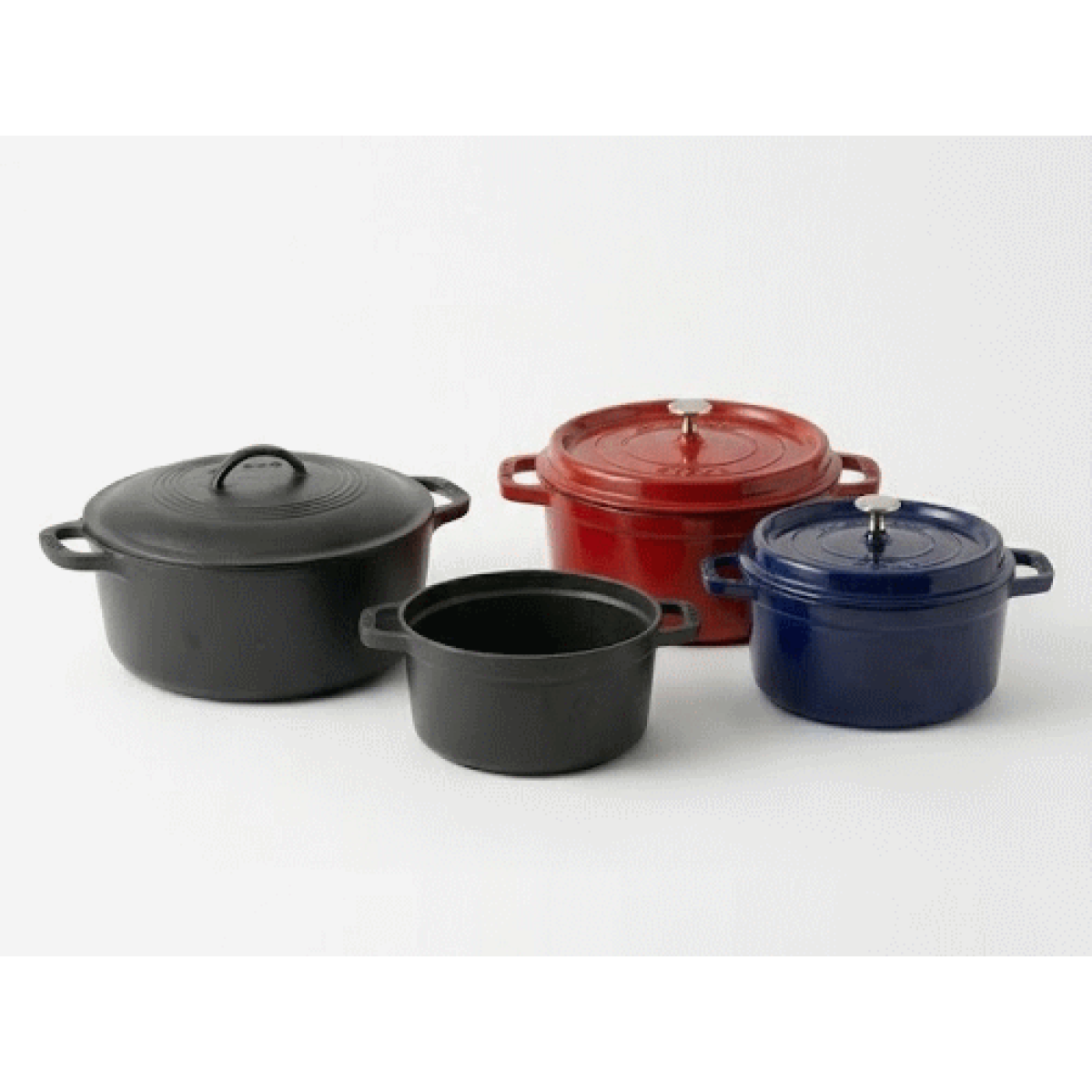
Application 1 — Dutch ovens (biscuit & fired, on cast iron)
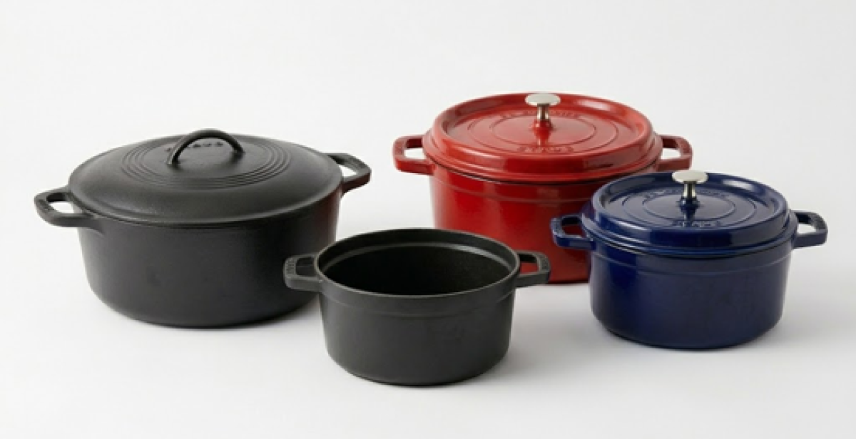
A first anticorrosion enamel layer on cast-iron Dutch ovens, applied by wet slurry and measured both at the dried biscuit state and after firing.
Ten samples were prepared at various enamel thickness levels. At the dried biscuit state, ten photothermal measurements were taken at different locations on each sample to extract the phaseshift; the samples were then fired and measured by cross-section microscopy as the destructive reference. Averaging per sample, the biscuit-state phaseshift correlates to the final fired thickness at 98.61% — so, once calibrated, the sensor predicts the fired thickness directly from a biscuit-state reading, with an average absolute difference of 1.4 µm to the cross-section. Repeating the test at the fired state gave a comparable 98.42% correlation (1.2 µm average difference). Similar results were obtained on the second, colour cover-coat layer.
Sensor parameters
|
98.6%
Correlation — biscuit state vs fired reference
|
1.4 µm
Average absolute difference to cross-section
|
|
98.4%
Correlation — fired state vs reference
|
1.2 µm
Average absolute difference to cross-section
|
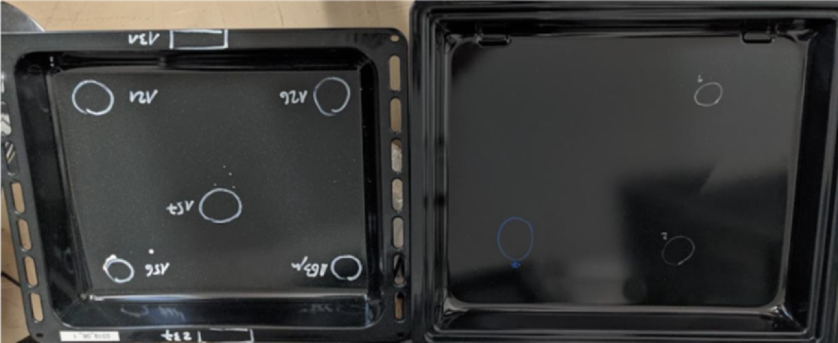
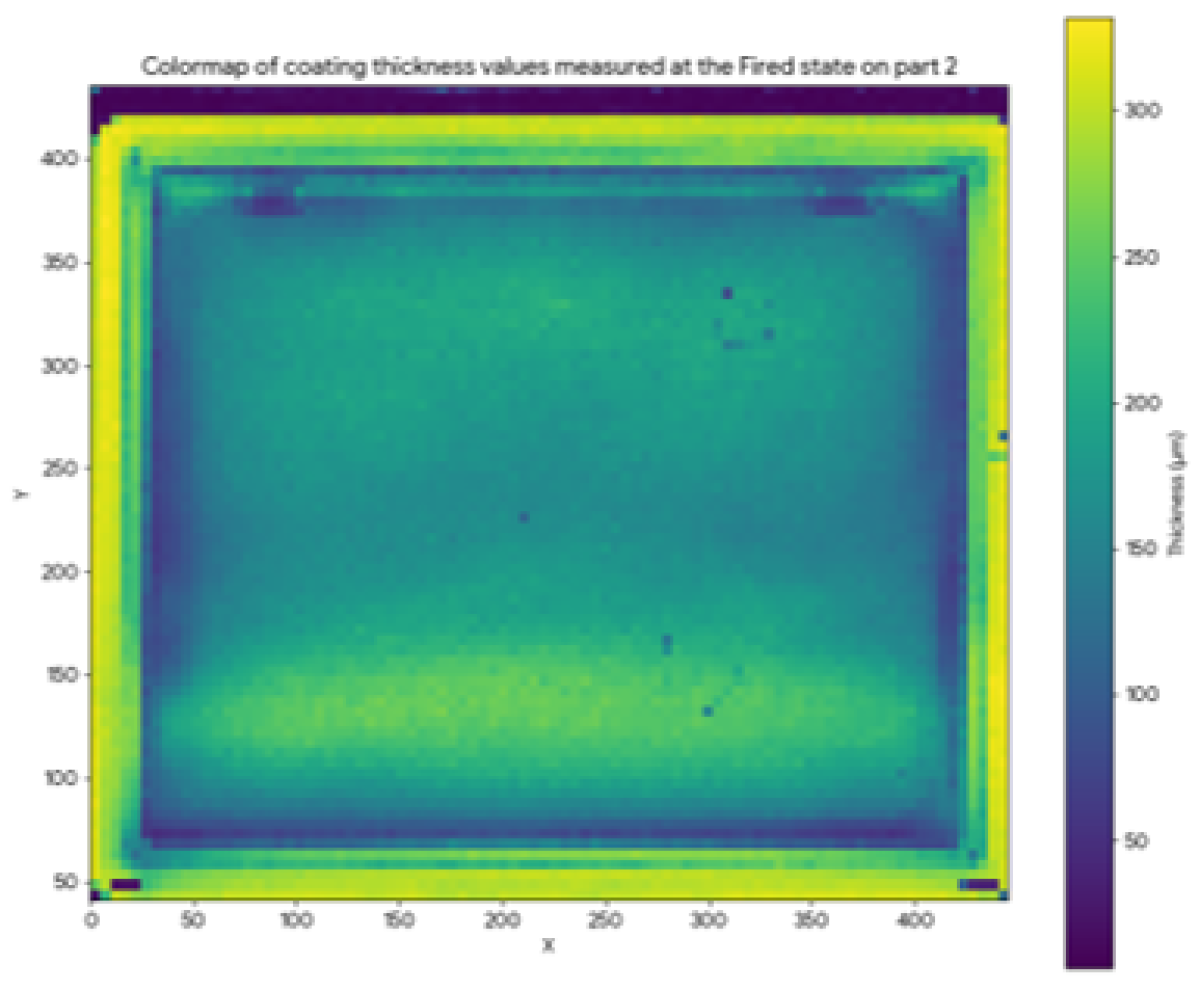
Application 2 — Oven trays (powder & fired, on steel)
A dry powder enamel coating on steel oven trays, mapped at the powder state and after firing. Eddy current cannot measure the powder state — contact would wipe the coating away — whereas photothermal maps the whole part and spots overspray at the bottom edge before any firing energy is spent.
Two trays were tested: Part 1 at the powder state, then fired and measured with an eddy-current reference, and Part 2 directly at the fired state.
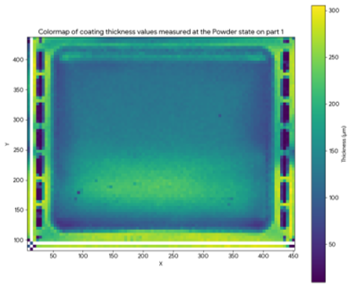
Correlating the powder-state photothermal readings on Part 1 to the eddy-current values across thickness areas from 100 to 350 µm gave a 96% correlation; the fired-state comparison on Part 2 reached 97%.
A full thickness map was also built at the powder state by stepping the Point sensor over a 5 mm grid covering the whole tray — the resulting colormap measured every position correctly and clearly revealed an overspray zone at the bottom of the part, all before any firing energy was spent.
Sensor parameters
|
96%
Correlation at powder state (100–350 µm, vs eddy current, fired)
|
97%
Correlation at fired state (100–350 µm, vs eddy current)
|
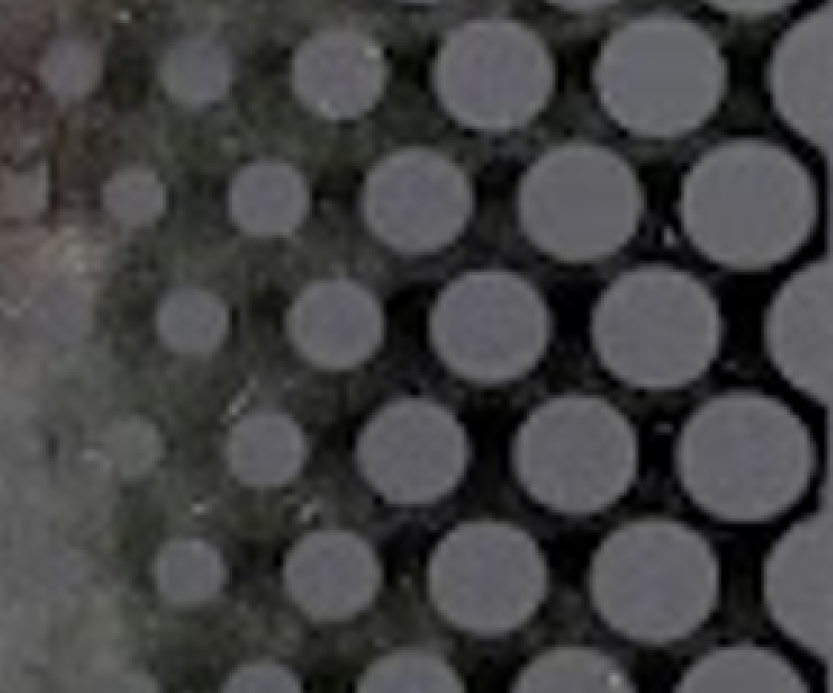
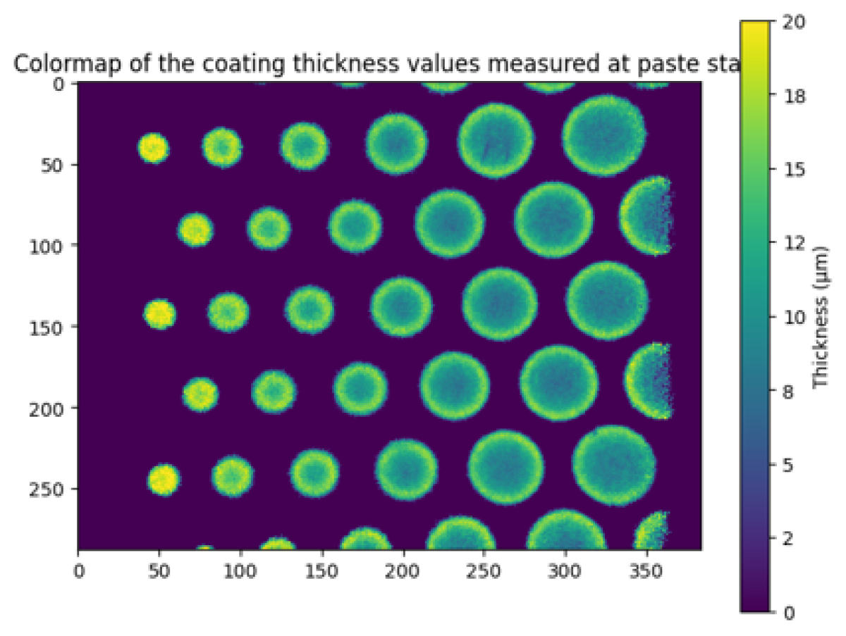
Application 3 — Vitroceramic glass (paste state)
A thin screen-printed enamel on vitroceramic glass — around 10 µm — captured at the paste state with the Field Sensor in a single full-field snapshot. No glass reference level is needed and no sensor movement is required; the field map resolves the raised edges on each printed dot, a typical screen-printing signature.
The conventional alternative on glass is to measure the height of the printed markings against the bare-glass level with a profile sensor — but this is only accurate close to the marking edges where a glass reference is available, requires mechanical movement and tilt referencing, and a contact probe is not advisable on the fragile paste. The Field Sensor instead images the whole 21 × 15 mm area in a single one-second snapshot: each of its 384 × 288 pixels returns a local thickness over a 55 µm spot. On a vitroceramic glass printed with dots of various sizes, measured before curing, the 1-second colormap resolves the raised bumps at the edge of each dot — a characteristic screen-printing pattern — with no glass reference level and no moving sensor.
Sensor parameters
|
110 592 pts
Full-field acquisition in a single snapshot
|
55 µm
Spatial resolution per pixel
|
Application 4 — Water-storage tanks (wet slip & fired, on steel)
Glass-lined steel water-storage tanks carry a heavy enamel layer applied as a wet slip and then fired. Controlling this lining is critical: a localised thin zone exposes the steel to corrosion over the life of the tank. The enamel was measured at two states — the wet-applied slip and the fired lining — against two independent reference techniques.
Sensor parameters
Wet state — compared against a wet-film disc contact gauge, the only conventional option on a fresh slip (and one that disturbs the film it measures):
Fired state — compared against eddy current on the fired lining, the sensor tracks the reference closely up to about 1 mm, beyond which the signal saturates:
06 — Industrial Integration
How to integrate Enovasense sensors on an enamelling line
Depending on whether measurement is needed off-line at quality control, as a high-resolution full-field map, or fully in-line on a powder enamelling conveyor, Enovasense offers three complementary integration routes built on the same patented LPTR sensor.
HKL — off-line control station
The HKL is a compact off-line control station for laboratory and end-of-line quality control. An Enovasense Point sensor is positioned over a series of measurement points across a part — or a batch of parts — to record thickness in a fast, repeatable sequence. It is the natural fit for cookware, tank components, and trays inspected at the quality lab, and benefits from the technology's low sensitivity to part position, curvature, and shape.
Field Sensor — full-field imaging in one snapshot
The Field Sensor is an all-in-one imaging head that captures 384 × 288 — 110 592 measurement points — in a single, roughly one-second acquisition at a 55 µm pixel size, with no moving sensor required. It is ideal for high-resolution thickness mapping and defect detection: resolving screen-printed prints on vitroceramic glass, or mapping overspray across a complete powder-coated panel.
HSR — turnkey in-line station for powder enamel
For automated in-line control on an electrostatic powder enamelling line, the HSR platform is a fully self-contained, turnkey measurement station installed alongside the conveyor — no external controller, power station, or water cooling required. A compact sensor head on a 3-axis motorized gantry, guided by a structured-laser tracking module, automatically detects parts as they move and runs the measurement sequence with no operator intervention, adapting to variable part geometries within a predefined grid.
Deployment steps (HSR)
Site preparation
Client provides a 230 V / 16 A power outlet and an Ethernet network point at the machine footprint location. No compressed air or water cooling required.
Design & engineering phase
Enovasense delivers mechanical implantation plans, electrical schematics, safety risk analysis (EN 13849-1), and functional description within 4 weeks of order.
Factory acceptance test
Reduced functional test performed at Enovasense premises before delivery to validate conformity of all HSR functions against specification.
Installation, commissioning & training
On-site installation and set-up of the full machine, followed by Expert, Operator, and Maintenance training sessions delivered on-site. Full documentation (CE certificate, user manuals, electrical and mechanical drawings) provided.
12-month warranty & ongoing support
Full machine warranty for 12 months after provisional acceptance, with 1-week intervention commitment. Optional annual maintenance contract covering hotline, preventive maintenance visit, and software updates.