Applications / in-line non-contact thickness measurement of coatings on epdm profiles
01 — Introduction
Coatings on EPDM door sealing profiles: a thin layer that decides perceived quality
Modern automotive door, window-frame and trunk seals are built around extruded EPDM (ethylene propylene diene monomer) profiles — a chemically inert elastomer that delivers the long-term resistance to water, dust, ozone and temperature cycles that automotive bodies require. To turn a bare EPDM profile into a finished sealing system, one or several thin coatings are applied just after extrusion, before the profile is cut, reeled and shipped to the assembly plant.
Several coating families are routinely deposited along an extrusion line, each addressing a different functional need:
Solvent slip-coat Water-based slip-coat GRC lacquer Adhesive primer Anti-friction topcoat
Slip-coats reduce friction between the seal and the moving glass or the painted body, which directly drives perceived door-closing effort and the absence of squeak noises. GRC (glass-run channel) lacquers add a thicker, structured layer at the glass-run interface to resist hundreds of thousands of opening cycles. Adhesive primers prepare the EPDM surface for subsequent flocking or for bonded assembly to other parts of the sealing system. Coatings are typically a few micrometres to a hundred micrometres thick — and their actual thickness drives the long-term behaviour of the seal in service.
Figure 1 — EPDM sealing profile production sequence
02 — Quality Requirements
Why coating thickness has become a 100% in-line specification
The actual coating thickness drives the long-term performance of an EPDM seal — and the in-spec window is narrow. Below it, the seal does not perform; above it, material is wasted and the coating itself is more prone to cracking. Three independent factors converge to make thickness the critical quality parameter of the entire production chain.
A function-critical layer with a narrow in-spec window
Too thin: friction is not properly reduced — door-closing forces rise, squeak risk increases and glass-run wear accelerates over the lifetime of the vehicle. Too thick: significant material is wasted across the multi-kilometre yearly profile runs that a sealing-system supplier produces, drying ovens are pushed out of spec, and the coating itself becomes more prone to cracking under repeated bending. The in-spec thickness window is typically only a few micrometres wide — and it must be respected over kilometres of running profile.
Coating uniformity along and around the profile
EPDM coatings are applied by spray nozzle, dip station or calibrated roller depending on the line architecture. All three deposition modes are sensitive to drift: paint viscosity, line speed, nozzle clogging, profile centring, oven temperature — every parameter directly affects the deposited film. The applied film is also rarely identical all the way around the cross-section of the profile: the geometry of the spray pattern, the orientation of the profile and the local geometry of complex sections (lips, bulbs, inserts) generate angular thickness variations that only point measurement at multiple positions can resolve.
OEM in-line measurement requirements
High-end OEMs are increasingly making 100% in-line, non-destructive coating-thickness measurement a written specification for new sealing-system tenders — no longer accepting the historical practice of one destructive cross-section per drum or per shift. Several premium German and Asian OEMs now require their EPDM profile suppliers to deliver a continuous, traceable thickness record on every metre of profile shipped. The reasoning is straightforward: a non-conformity detected on a sample taken from one drum does not protect the next several hundred metres of profile already coated, packaged and shipped. Continuous in-line measurement is the only way to deliver the traceability and the closed-loop process control that a modern OEM expects from its tier-1 supplier.
|
< 1 µm
Reproducibility achieved on EPDM coatings (depending on the optical system selected and the layer thickness)
|
> 99 %
Linear correlation R² with the destructive reference measurement
|
|
1 / 5 s
Typical in-line measurement cadence — faster configurations available
|
100 %
In-line coverage — every metre of profile, every coating run, in real time
|
03 — Measurement Challenges
Why conventional inspection methods cannot deliver in-line thickness control
Two methods are widely used today on EPDM coating lines. Each addresses part of the problem; neither delivers the continuous, quantitative, non-destructive thickness data that an OEM specification now requires.
Destructive cross-section microscopy
Cross-section microscopy is the reference method for absolute coating thickness on EPDM. A length of profile is cut and measured under an optical microscope. The result is accurate and traceable — but each measurement requires up to one hour of skilled operator time per sample, the sampled section of profile is destroyed and cannot be sold, and the measurement only becomes available tens of minutes after the profile was actually coated. As a consequence, profile manufacturers historically rely on widely-spaced destructive checks (one per drum, one per shift) — leaving long stretches of running profile uncontrolled in between, and detecting drift only long after thousands of metres of out-of-spec material have already shipped.
UV inspection and fluorescent tracer verification
A common shop-floor practice is to add a fluorescent tracer to the coating formulation and visually inspect the running profile under UV light. This method confirms only the presence or absence of the coating layer — it cannot quantify how thick it is. A profile carrying a 3 µm slip-coat fluoresces just as brightly as a profile carrying a 25 µm coat, even though the second profile has consumed more than eight times the material and behaves very differently in service. UV inspection therefore catches only catastrophic defects — a coating-gun stoppage, a lost section — and is structurally blind to the thickness drift that an OEM specification now requires the supplier to monitor and to feed back into the deposition process.
The case for non-contact, in-line, quantitative inspection
Measuring quantitatively, non-destructively and at every metre of running profile transforms the quality paradigm:
- Quantitative thickness in micrometres — not just a binary presence/absence verdict.
- Non-destructive and contactless — the freshly coated, soft EPDM surface is never touched, and every metre of profile is sold.
- Continuous and in-line — drift is detected after a handful of metres rather than after a full drum, allowing immediate corrective action on the deposition station.
- Closed-loop feedback — the measurement value is sent in real time to the line PLC and to the plant MES.
- OEM-spec compatible — full traceability of every metre, in line with the in-line measurement clauses of premium-OEM tendering specifications.
04 — Technology Comparison
Why laser photothermal radiometry is the ideal solution
Enovasense's patented laser photothermal radiometry resolves the limitations of the existing methods in a single sensor. A modulated laser beam heats the surface of the coating; an infrared detector captures the temporal profile of the back-emitted thermal flux; the coating thickness is extracted from the characteristic delay of that thermal response. The method is fully non-contact, non-destructive, quantitative, and compatible with the speeds and geometries of an EPDM extrusion line.
Validated technology — patent protected. Enovasense laser photothermal radiometry is a patented measurement principle, validated through industrial trials at European tier-1 sealing-system suppliers on solvent and water-based slip-coats as well as thicker GRC-type lacquers, on smooth and structured coating finishes, and at the typical line speeds of EPDM profile extrusion.
| Criteria | Enovasense laser photothermal | Cross-section microscopy | UV / fluorescent tracer |
|---|---|---|---|
| Non-contact measurement | Yes | No — profile is cut | Yes |
| Non-destructive | Yes | No — sample destroyed | Yes |
| Quantitative thickness in µm | Yes — every metre | Yes — reference method | No — presence only |
| Compatible with OEM in-line specification | Yes | No — sampling only | Partial — no thickness data |
| 100% inspection coverage | Achievable | No — ≈ 1 sample / shift | Binary only |
| Reproducibility (standard deviation) | < 1 µm | Reference method | Not applicable |
| Per-sample operator time | None — automatic | 1 to 2 h per sample | Visual inspection |
| Closed-loop feedback to coating station | Yes — real-time data to MES | No — delayed by hours/days | No |
Reproducibility values depend on the optical system selected and on the layer thickness. Cross-section microscopy is used as the destructive reference method for the calibration regression.
05 — Metrological Performance
Validated accuracy and sub-micrometric repeatability on EPDM
The performance of Enovasense laser photothermal radiometry on EPDM coatings has been validated through a calibration study performed on a set of reference samples covering the full thickness range relevant to automotive sealing applications, and through industrial trials directly on a customer extrusion line.
The reproducibility and accuracy figures reported below correspond to a representative configuration for slip-coat measurement on EPDM. Actual performance on a given application depends on the optical system selected (focal length, numerical aperture, laser parameters) and on the thickness range of the coating measured.
Calibration regression: linearity vs the destructive reference
Five reference samples spanning 4.8 µm to 24.4 µm of slip-coat on EPDM substrate were measured by ball-micrometer (reference method) and by Enovasense laser photothermal sensor. The sensor was calibrated against the reference values; for each sample, ten verification points were averaged and compared to the reference average. The resulting correlation is shown in Figure 2.
Figure 2 — Calibration: Enovasense vs ball-micrometer reference
5 reference samples (4.8, 9.6, 15.6, 20.4, 24.4 µm) — Enovasense average from 10 verification points per sample compared against ball-micrometer reference average from 5 points per sample.
The linear regression delivers a coefficient of determination R² = 99.14 %, confirming that a single linear calibration curve covers the full thickness range with residuals consistent with the sampling noise of the reference method itself. A correlation above 99 % across more than five times the thinnest sample's value is the metrological foundation that makes in-line process control credible.
Repeatability: sub-micrometric standard deviation
Repeatability was assessed by performing ten consecutive measurements at exactly the same point on a 14.5 µm sample. The dispersion of those ten measurements characterises how finely the sensor can resolve a real process drift on the production line.
Figure 3 — Repeatability: 10 consecutive measurements at the same point
Ten successive Enovasense measurements at the same point — standard deviation 0.88 µm on a coating of approximately 14.5 µm, more than an order of magnitude better than the resolution typically required for in-line slip-coat control.
With a standard deviation of 0.88 µm on a coating of about 14.5 µm, the Enovasense sensor delivers a sub-micrometric repeatability that allows the detection of process drift well below the typical tolerance band of an EPDM slip-coat specification. This margin is decisive for closed-loop process control: it allows nozzle wear, viscosity drift and line-speed fluctuations to be detected and corrected before they generate non-conforming material.
In-line validation on a running EPDM extrusion line
Beyond the off-line calibration study, the technology has been validated through industrial trials directly on a customer EPDM extrusion line, with the sensor installed a few metres downstream of the coating station. The takeaways from those trials:
- Successful continuous measurement on both smooth and structured coating surface finishes.
- Validated on multiple coating chemistries — solvent and water-based slip-coats, as well as thicker GRC-type lacquers in the ~100 µm range.
- No influence of profile temperature variations: the measurement is robust to the residual heat of the freshly coated profile after curing.
- Different thicknesses correctly resolved at different angular positions around the cross-section of the profile.
- Typical line configuration: 35 mm working distance, 1 measurement every 5 seconds, compact sensor footprint, contactless interaction with the freshly coated profile.
- Plug-and-play deployment, intuitive software, operator-ready from day one.
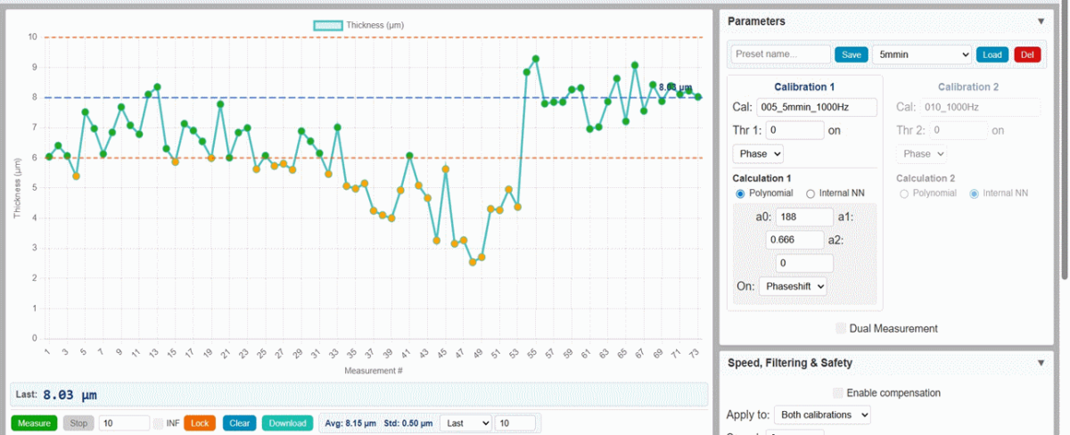
View of the in-line software interface featuring measurement statistics, tolerances setting and alarm on significant drifts
06 — Industrial Integration
Two deployment levels — from manual holder to fully automated 360° turnkey
Depending on the customer's existing line, the available footprint and the required level of automation, Enovasense offers two deployment levels for in-line EPDM coating thickness measurement. Both levels share the same compact, plug-and-play sensor and the same supervision software — only the integration around the sensor changes.
Level 1 — Manual holder with measuring head
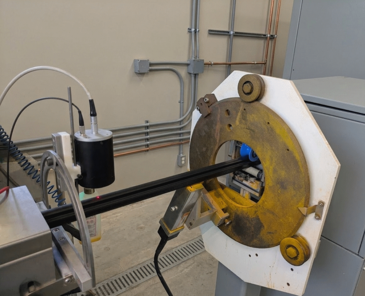
The simplest in-line integration: the compact sensor is fixed on a holder positioned a few metres downstream of the coating station, where the operator can manually rotate it around the running profile to inspect different angular positions on demand. No robot, no actuator — single sensor, mechanical holder, fast deployment on existing extrusion lines, no major retrofit. The freshly coated profile is never touched.
Level 2 — Fully automated 360° turnkey solution
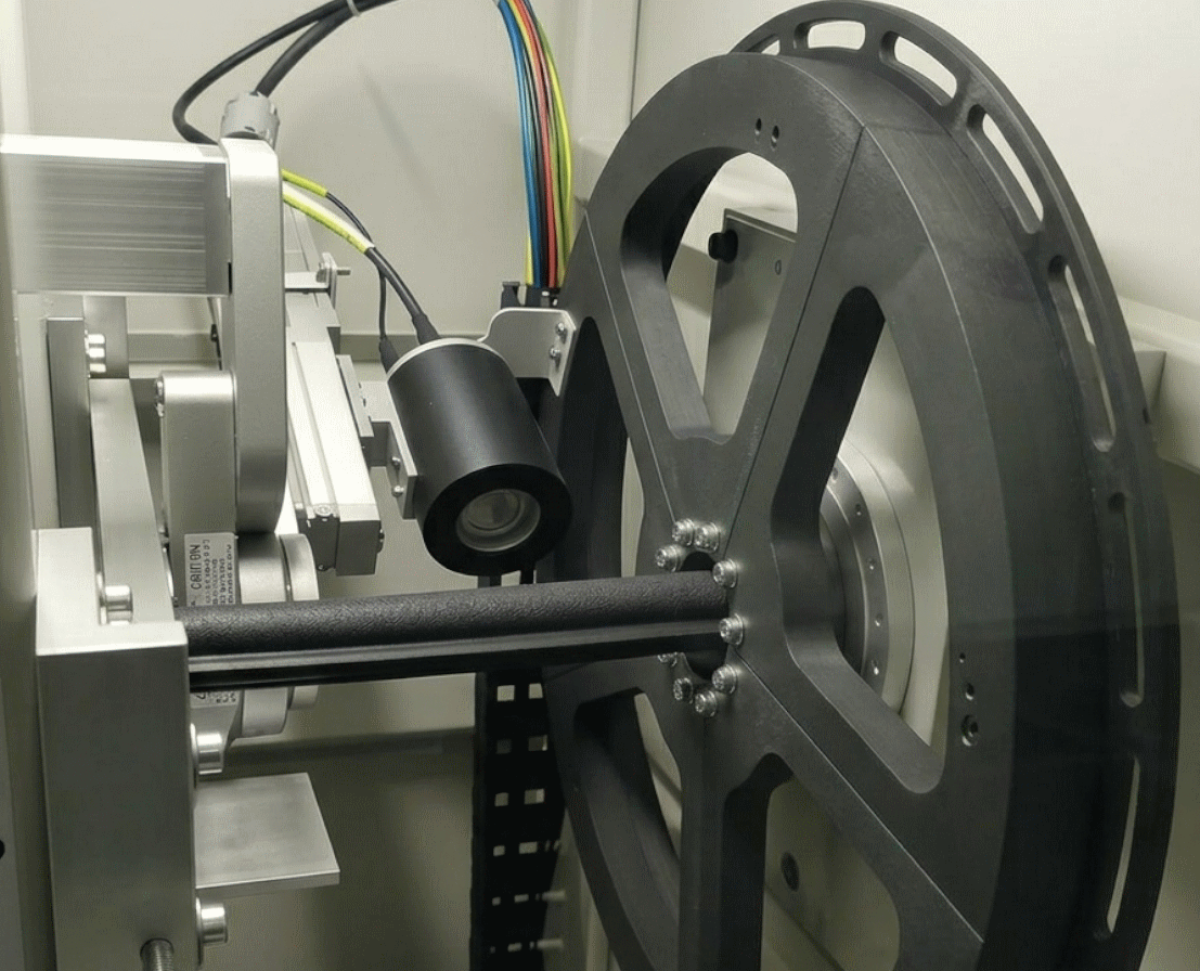
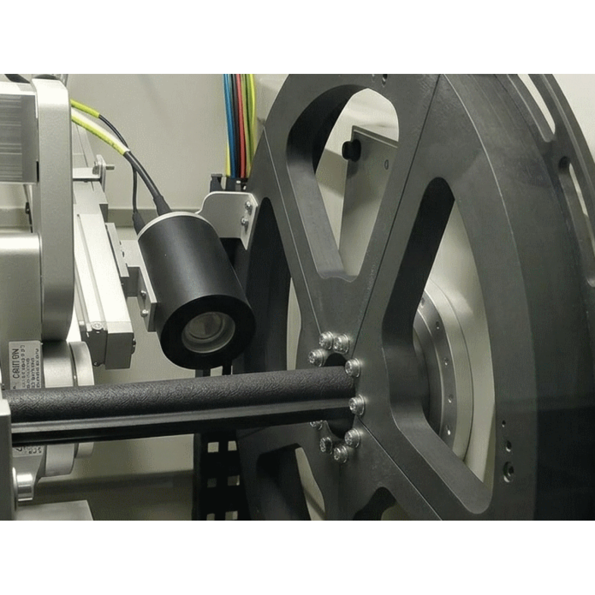
For full-circumference angular thickness mapping on a continuous running profile, Enovasense delivers a turnkey rotative station built around three mechanically decoupled structures, integrating the sensor on a motorised 360° rotation axis, a profile-shape detection module that measures the local geometry of the EPDM section in real time, an active distance-control loop that keeps the sensor at the nominal working distance regardless of profile movement or transient line-speed changes, and the dedicated supervision software — delivered as a single, ready-to-run unit installed downstream of the coating station.
Figure 4 — 360° turnkey station architecture
The compact Enovasense sensor
At the heart of every deployment level is the same compact, plug-and-play sensor. The sensor combines a modulated laser source, the optical path that focuses the beam on the profile and collects the IR thermal flux, and the electronics that extract the thickness from the temporal profile of the thermal response. The optical configuration (focal length, spot size, working distance, modulation parameters) is selected on a per-application basis to optimise reproducibility, accuracy and integration constraints.
Technical specifications — Enovasense in-line sensor for EPDM coatings
| Measurement principle | Laser photothermal radiometry — fully contactless |
| Typical thickness range on EPDM | ~ 1 µm to ~ 120 µm (slip-coats, primers, GRC lacquers) |
| Reproducibility (σ) | < 1 µm (depends on optical system selected and layer thickness) |
| Correlation R² with destructive reference | > 99 % across the full thickness range tested |
| Working distance | ~ 35 mm typical (configurable) |
| Spot size | From sub-millimetre to several millimetres (optics-dependent) |
| Laser source | 1550 nm — 6 W (other wavelengths available on request) |
| Measurement rate | 1 measurement / 5 s typical — faster configurations available |
| Profile-temperature tolerance | No influence on the measurement within typical post-curing temperatures |
| Software features | Live thickness curve, calibration management, pass/fail thresholds, automatic data logging, CSV export |
| Data interface | Ethernet TCP/IP — MES / SPC integration, CSV export |
| Integration options | Manual holder / fully automated 360° turnkey station |
Specifications are indicative and can be adapted to specific customer requirements.

 Deutsch
 Español
 Français
 Italiano
 日本語
日本語
 한국어
한국어
 Polski
 中文
中文