Products / high resolution non-contact under-surface area analysis - field sensor hr
01 — Product Overview
Enovasense Field Sensor HR
Non-contact under-surface area analysis — 110,592 points in a single shot
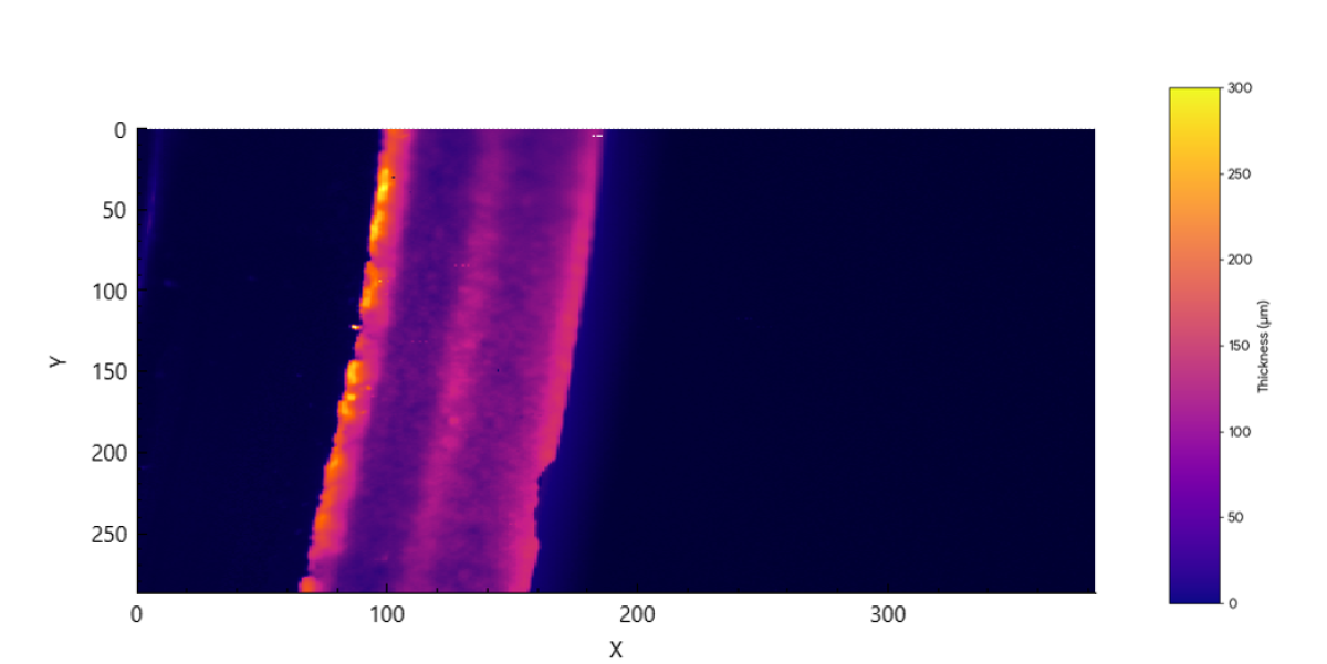
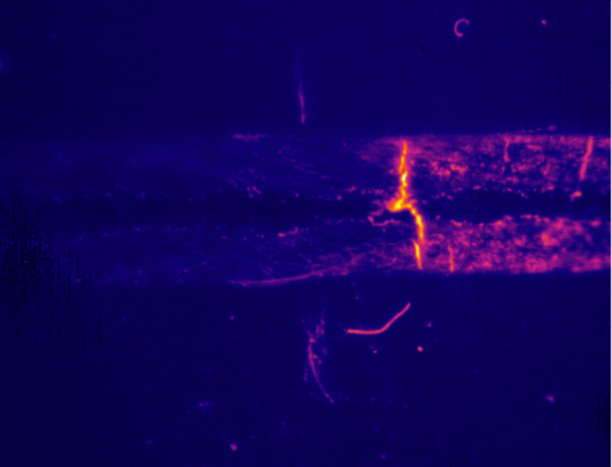
The Enovasense Field Sensor HR is a laser photothermal imaging instrument that analyses an entire surface at once — fully non-contact, fully non-destructive, in a few seconds. Instead of probing one point at a time, the Field Sensor HR illuminates a full zone of the part, captures the thermal response through a dedicated IR detector array, and returns a 384 × 288 image of what lies under the top surface.
It is used to detect cracks, pin-holes, delaminations, bad adhesion, false-friend welds, air gaps and changes of material that are invisible to vision systems — and to map coating thickness over the whole surface of a part, with no automation, at a resolution down to 29 µm per pixel.
Non-contact Non-destructive Full-field imaging 110,592 points / shot No automation needed Under-surface defects
|
110,592 pts
Points captured in a single shot on a 384 × 288 matrix
a full surface analysed in down to 1 second
|
55 µm
Spatial resolution per pixel on the HR55 variant
29 µm and 120 µm variants also available
|
|
21×16mm
Field of view analysed in a single acquisition (HR55)
up to 46 × 33 mm on the HR120 variant
|
1-1000µm
Thickness mapping range on a wide variety of coatings
plus qualitative defect detection
|
02 — Why choose the Field Sensor HR
Five reasons this sensor earns its place on a production line
1. Non-contact, non-destructive, and substrate-agnostic
The sensor works by sending a modulated laser beam onto the part and analysing the infrared thermal response with a built-in detector array. No probe tip touches the part, no sample is cut, no X-ray is emitted. The method is insensitive to the electrical or magnetic nature of the substrate — it works on metals, aluminium, steel, polymers, glass, and composites, and it tolerates dry or wet/uncured coatings and hot or cold parts.
2. An entire surface in a single shot — no automation required
Where a point sensor requires an XY stage or a robot to build a map, the Field Sensor HR captures the full field of view at once. Over 100,000 pixels are acquired in down to a second, each one an independent photothermal measurement. Thickness maps, defect maps and adhesion maps that used to need a full scanning station are now obtained with a fixed sensor and a static part.
3. Sees what vision systems cannot — under-surface defects
The signal is thermal, not optical. A weld that looks perfectly good on a camera but is not bonded underneath (a "false-friend" weld) is invisible to machine vision — but stands out immediately on the Field Sensor HR image, because heat cannot diffuse through the missing contact. The same principle catches air gaps, delaminations, sub-surface cracks, pin-holes, bad adhesion and changes of material.
4. Tolerant to real industrial geometries
The sensor works on flat parts, on curved parts and at inclined angles up to ±50°, with a distance tolerance of ±1 mm up to ±10 mm depending on the application. Roughness, surface finish and part temperature are not blocking factors — making the Field Sensor HR usable directly on production parts, without surface preparation.
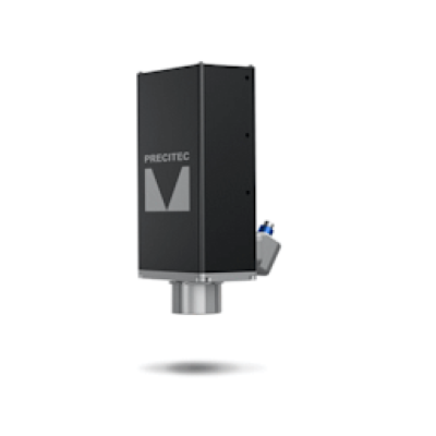
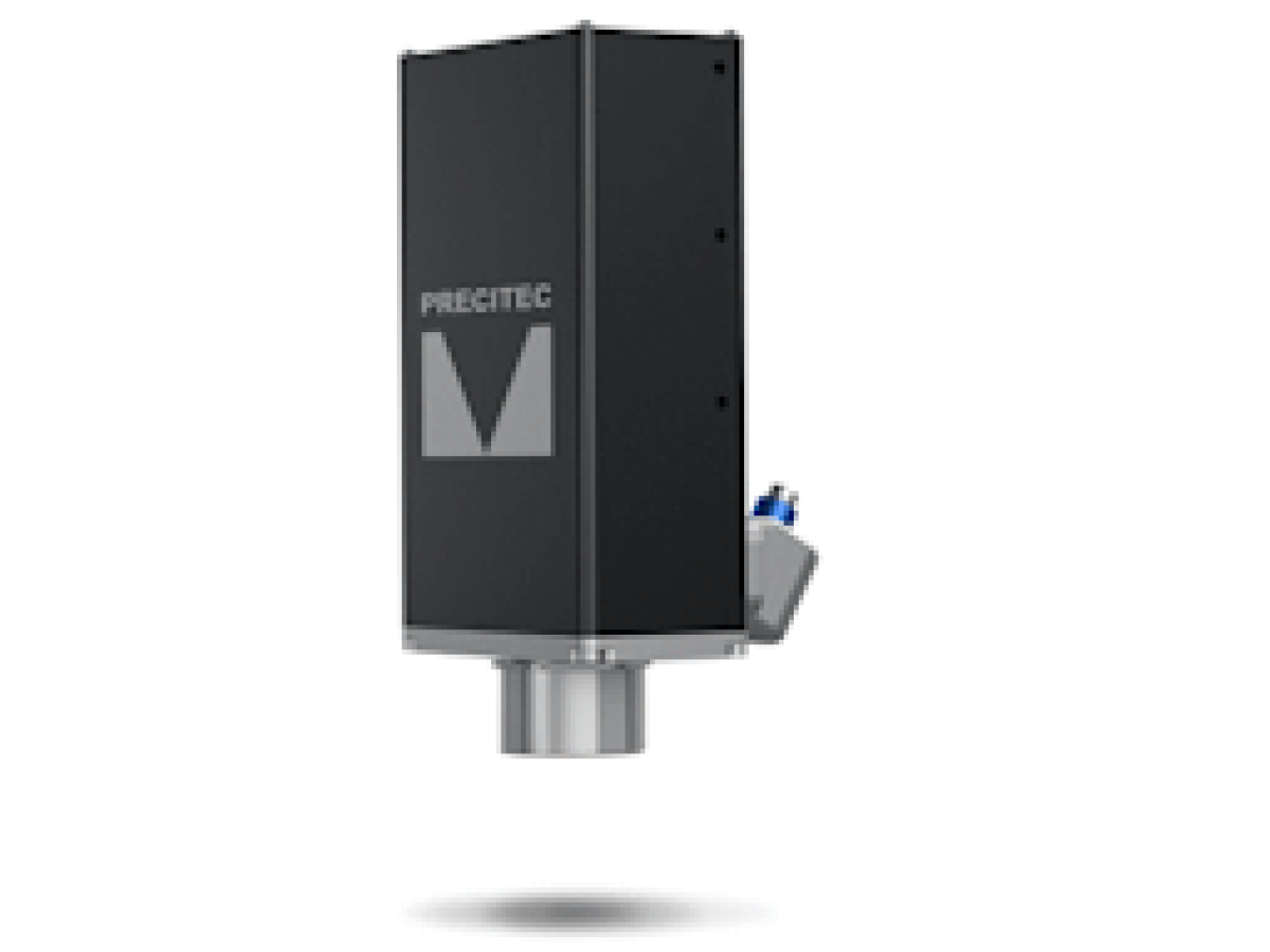
5. Compact head, standard 19" controller, easy integration
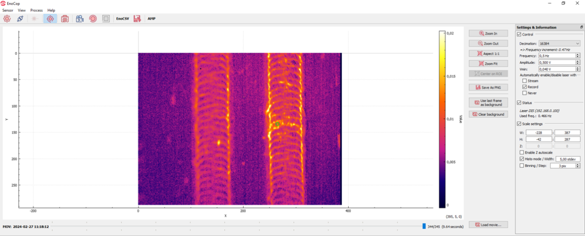
The measurement probe is a single compact block of 93 × 85 × 174 mm (400 g) that is placed facing the part. The controller is a standard 19" 3U rack unit (6 kg, 100–230 V AC) that can sit in an electrical cabinet up to 10 m away, linked to the head by one optical fiber and one electric cable. Ethernet TCP/IP output feeds the dedicated Enovasense Suite software, which also includes an ANN module to train automatic pass/fail classification.
03 — Applications
Where the Field Sensor HR is used
The Field Sensor HR is used whenever an area — not a point — has to be characterised: defect detection on welds and joints, quality control of bonded assemblies, full-surface coating-thickness mapping, and inspection of parts where sub-surface information is critical. Typical deployments include:
| Automotive & e-mobility | False-friend weld detection, air-gap detection on laser and ultrasonic welds, bonding inspection on battery busbars, paint and primer thickness mapping |
| Aerospace | Thickness mapping of thermal barrier and abradable coatings, delamination detection on composite and bonded structures, cold-spray repair inspection |
| Medical devices | Full-surface check of bioactive and polymer coatings on implants, detection of pin-holes and coating defects on surgical tools |
| General industry | FKM and elastomer sealing thickness mapping on stainless steel, enamel marking on glass, rubber coating homogeneity, screen-printing inks |
| Consumer electronics | Inspection through epoxy insulation to verify presence and position of sub-components |
| Semiconductor | Surface crack and pin-hole detection on wafers |
04 — Technology
How full-field laser photothermal imaging works
A modulated laser beam is emitted onto a 21 × 16 mm zone of the part, generating a controlled thermal wave that diffuses into the material. An IR detector array inside the probe captures the returning heat wave for every pixel of the scene, and for each pixel extracts two physical quantities — the phaseshift and the amplitude ratio between the thermal response and the laser modulation. The result is a full 384 × 288 image of the sub-surface behaviour of the part.
Because heat diffusion is locally disturbed by anything that breaks the thermal continuity of the material, the image reveals what lies underneath the top surface: a coating interface (thickness mapping), a crack or pin-hole (surface defect), an air gap or delamination (weld quality), a sub-component hidden under an epoxy layer, or a false-friend weld where heat cannot cross the unbonded interface.
VIDEO : LASER PHOTOTHERMAL MEASUREMENT PRINCIPLE
Why this technology — a summary
Photothermal imaging is fully optical and thermal: no contact with the part, no electrical or magnetic coupling, no ionising radiation. The sensor is indifferent to the magnetic properties of the substrate, to surface roughness (within a large range), to part geometry (flat, curved, inclined up to ±50°) and to the production environment (hot or cold parts, dry or wet/uncured coatings). Calibration is built from representative reference samples once, and then reused in production indefinitely.
05 — Technical Specifications
Full technical datasheet — Field Sensor HR55 configuration
Key performance parameters
| Measurable thickness range (Ep) | 1 – 2000 µm (coating thickness mapping) |
| Field of view | 21 mm × 16 mm |
| Spatial resolution | 55 µm per pixel |
| Matrix size | 384 × 288 — 110,592 points per acquisition |
| Measuring rate | 1 Hz to 10 Hz for the full 110,592-point image |
| Angle tolerance | ±5° to ±50° (depends on application) |
| Distance tolerance | ±1 mm to ±10 mm (depends on application) |
| Working distance | 50 mm (fixed) |
Measurement probe — mechanical & optical characteristics
| Probe dimensions (Lh × Wh × Hh) | 93 × 85 × 174 mm |
| Probe weight | 400 g |
| Laser wavelength (λ) | 980 nm |
| Maximum laser power | 150 W (maximum laser intensity: 1.22 W/mm²) |
| Laser class | Class 4 (IEC 60825-1) |
| Probe operating temperature | < 35 °C ambient |
Controller / computing unit
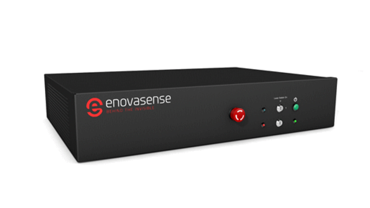
| Controller format | 19" rack, 3U |
| Controller dimensions (W × L × H) | 444 × 310 × 133 mm |
| Controller weight | 6 kg (datasheet) — up to 10 kg with options |
| Power supply | 100–230 V AC / 50–60 Hz |
| Data interface | Ethernet TCP/IP — Enovasense Suite software — MES / SPC compatible |
| Safety — interlock connector | Laser locker / safety loop ready |
| Operating temperature | +5 °C to +50 °C |
| Optical fiber between head and controller | 2 – 10 m, minimum curvature radius 50 mm |
| Electric cable between head and controller | 2 – 10 m, RJ45 |
All values are typical. The actual performance depends on the application and on the target coating or defect. Please contact Enovasense for a performance diagnosis on your specific samples.
06 — Product Structure
An integrated sensor — head, controller and software in one delivery
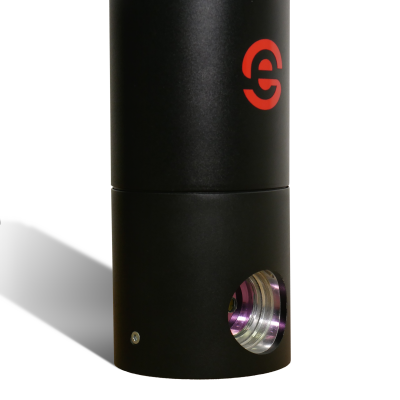
Unlike the Enovasense Point Sensor, the Field Sensor HR is delivered as a fully integrated system: the measurement probe, the controller, the connecting cables and the software suite are all part of a single reference. Integration into a production cell is straightforward — place the head facing the part and install the controller in a cabinet up to 10 m away.
Figure 2 — The four elements of a complete Enovasense Field Sensor HR system
Three field-of-view variants available. The Field Sensor HR comes in three versions sharing the same controller, matrix size and working distance — only the front optics change. Choose the variant that matches your target defect size and the area you need to cover.
07 — Available Variants
Choose the right Field Sensor HR for your application
Three variants are available — they differ by field of view and spatial resolution, while sharing the same 384 × 288 matrix, the same 50 mm working distance and the same 150 W, 980 nm laser source. Use HR29 for small, high-resolution inspections; HR55 for the most common applications; HR120 for large-area coverage in a single shot.
| Variant | Field of view | Spatial resolution | Working distance | Typical use |
|---|---|---|---|---|
| HR29 | 11 × 9 mm | 29 µm | 50 mm | Fine-defect detection, small features, high-resolution maps |
| HR55 | 21 × 16 mm | 55 µm | 50 mm | General-purpose variant — best balance between field and resolution (ref. 5105791) |
| HR120 | 46 × 33 mm | 120 µm | 50 mm | Large-area inspection, full-weld seam coverage, big parts in one shot |
All three variants share the 384 × 288 detector matrix, the 50 mm working distance, the 980 nm laser source with 150 W maximum power, the 19" 3U controller, the ±50° angle tolerance and the same Enovasense Suite software.
Package content
A complete Field Sensor HR system is delivered as a single reference and includes:
| Designation | Quantity |
|---|---|
| Enovasense Field Sensor HR measurement probe | 1 |
| Enovasense Field Sensor HR controller (19" 3U) | 1 |
| Optical fiber between probe and controller | 1 |
| RJ45 electric cable between probe and controller | 1 |
| Power cable | 1 |
| Enovasense Suite software (Eno2D — Launcher, Capture, Viewer, ANN, Quick) | 1 |
| 1-year warranty, CE certificate, quality control certificate | 1 |
08 — Accessories and options
A few complementary services and accessories are available to support deployment and maintenance of the Field Sensor HR:
| Reference | Accessory / service |
|---|---|
| 5105893 | Annual maintenance service — sensor |
| 5105894 | Annual maintenance service — control station |
| 5105895 | Delivery and installation pack |
The Field Sensor HR uses a fixed front lens and a fixed 50 mm working distance — there is no optical-tool selection as with the Point Sensor. Custom integration brackets, laser-safety enclosures and application engineering support are available on request.
09 — Optional Integration
From sensor to turnkey control station
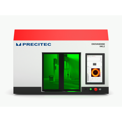
Because the Field Sensor HR emits a Class 4 laser, it is normally deployed inside an enclosure that keeps the Nominal Ocular Hazard Area unreachable to the operator. Enovasense can supply the sensor integrated into one of four Enovasense control stations — which include a safe enclosure, an automated positioning system, a PC and a dedicated HMI — turning the raw sensor into a turnkey laboratory, by-the-line or in-line inspection solution. The sensor itself must be ordered separately from the station.
| Reference | Name | Automation | Footprint (L × W × H) | Typical use |
|---|---|---|---|---|
| 5104906 | HKL | 3-axis Cartesian | 825 × 1282 × 943 mm | Lab / R&D / QA benches for flat or simple parts |
| 5105790 | HKL-R | 6-axis robot | 1025 × 1282 × 943 mm | Complex 3D parts — aerospace, turbines, medical implants |
Need help defining your inspection? The Field Sensor HR excels at area analysis — but the right variant (HR29, HR55 or HR120) and the right integration depend on your defect size, part geometry and cycle time. Contact Enovasense with your samples or a description of the defect you want to catch — we will propose the best combination of Field Sensor variant, software processing and, if needed, control station.
References
| Réference | Name | Status / Price | Datasheet |
|---|---|---|---|
| DATASHEET FIELD SENSOR | High Resolution Non-Contact Under-Surface Analysis - Field Sensor HR |
Available
On quotation |
English |