Products / coatings thickness measurement sensor - compact probe t033
01 — Product Overview
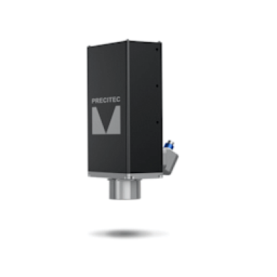
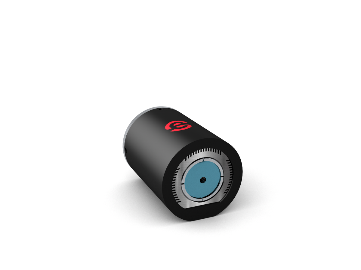
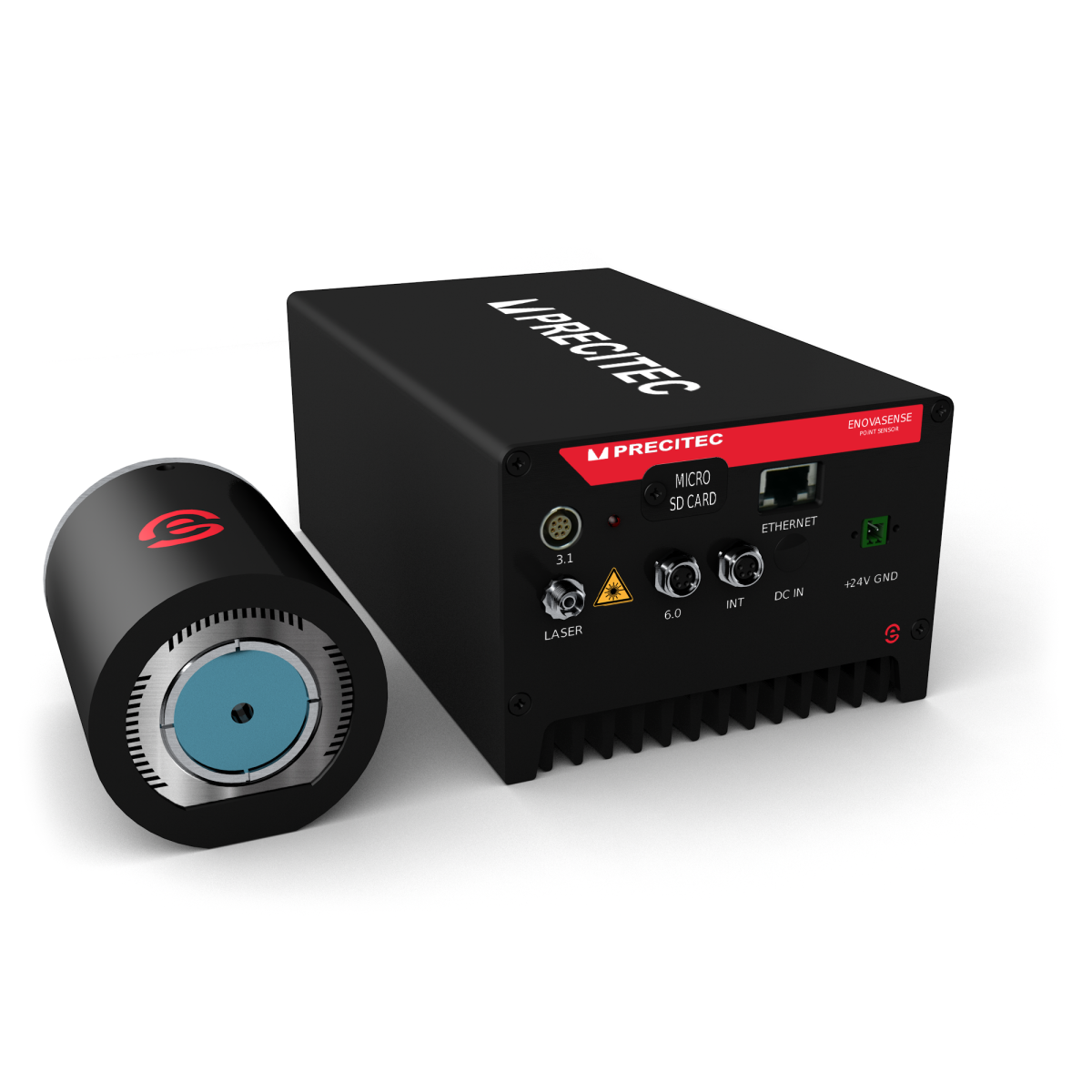
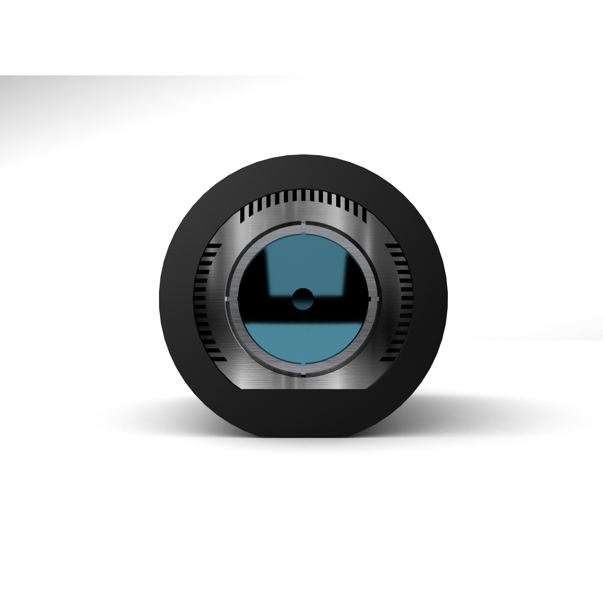
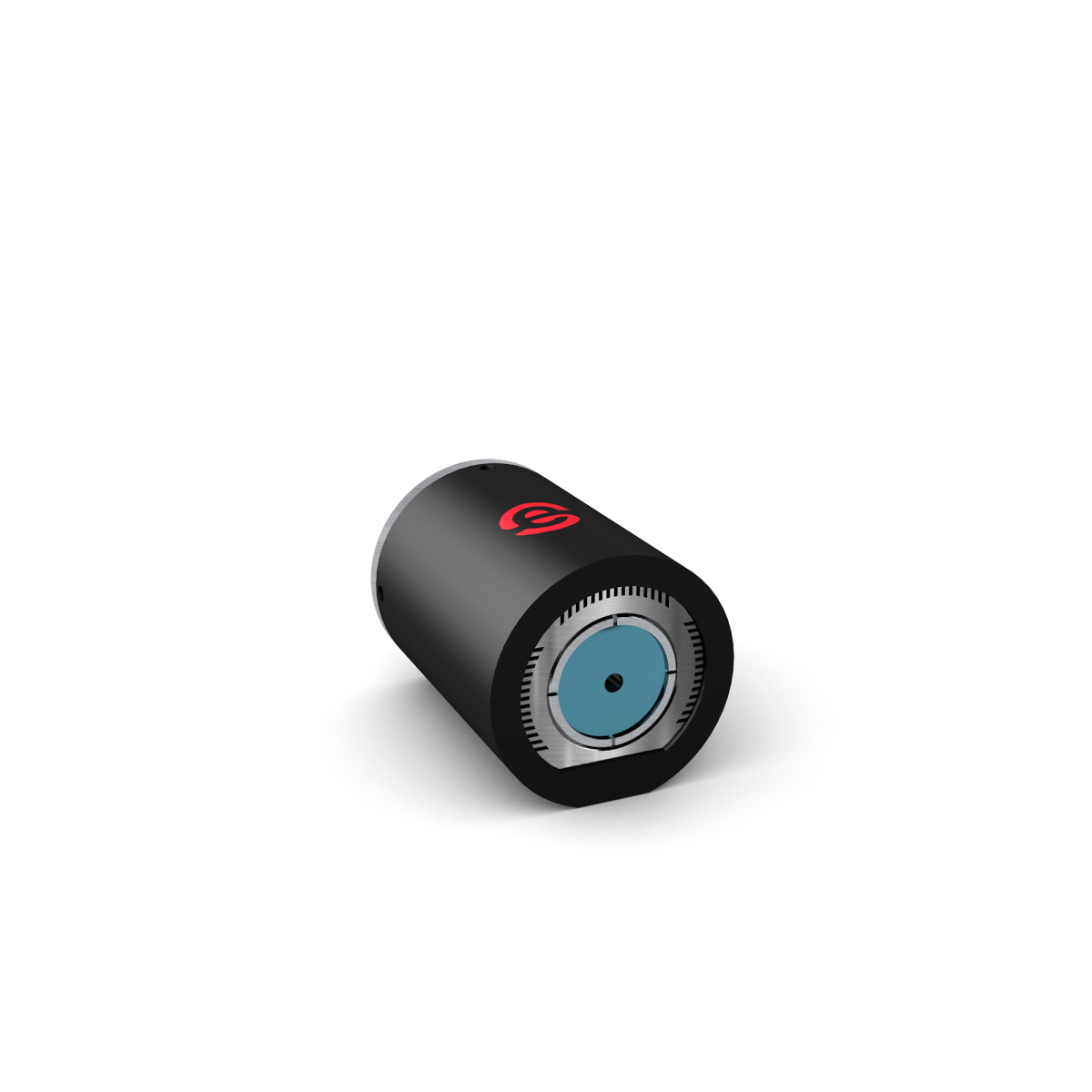
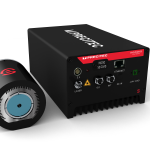
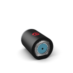
Enovasense Point Sensor with T033 probe
Non-contact coating thickness measurement from 10 nm to 1 mm
The Enovasense Point Sensor is a laser photothermal radiometry instrument that measures the thickness of a coating on a part — fully non-contact, fully non-destructive, in real time. The T033 probe is our standard workhorse head, suitable for the vast majority of lab and production use cases: it accepts the widest range of optical tools (simple lenses, magnetic mounts, 90° mirror heads, long working-distance objectives) and covers every laser power from 1 W to 150 W.
It measures paint, polymers, adhesives, anodizing, electroplating, thermal spray, cold spray, HVOF, PVD, CVD, PACVD, galvanizing, and screen-printing deposits on virtually any substrate — with a thickness envelope from 10 nm up to 1 mm on a single platform.
Non-contact Non-destructive Real-time 10 nm → 1 mm range Any substrate Lab & in-line
|
10nm-1mm
Measurable thickness range on a single platform
the widest span available on the market
|
<3%
Typical accuracy of the measured thickness
depends on the optical system selected and the coating
|
|
100-1000ms
Measurement duration per point
compatible with in-line cycle times
|
10-150mm
Measurement distance range available with various optical tools
the probe never touches the sample
|
02 — Why choose the T033 point sensor
Six reasons this sensor earns its place on a production line
1. Non-contact, non-destructive, and substrate-agnostic
The sensor works by sending a modulated laser beam onto the coating and analysing the infrared thermal response with a built-in detector. No probe tip touches the part, so there is no risk of scratching a fresh paint layer or a soft polymer; and no sample is cut, so 100% of the production can be inspected instead of a destructive sample every thousand parts. The method is insensitive to the electrical or magnetic nature of the substrate — it works on metals, aluminium, steel, polymers, glass, and composites.
2. One sensor covers an unusually wide thickness range
From a 10 nm PVD layer up to a 1 mm thermal spray deposit, a single T033 point sensor — configured with the right optical tool and the right laser module — covers the full envelope. This replaces the 2 or 3 complementary instruments typically needed when mixing eddy-current, ultrasonic, and X-ray gauges.
3. Real-time output, ready for closed-loop control
Each measurement takes from 100 ms to 1 s depending on the application. Results stream out in real time via Ethernet/TCP-IP and can be fed directly into an MES, an SPC system, or a closed-loop spray recipe. Coating process drift is caught in seconds, not in thousands of parts.
4. Proven in automotive, aerospace, medical, and electronics
The technology is deployed worldwide for critical coating measurements — including a joint patent with Renault Group (EP3781902B1) on the use of laser photothermal radiometry inside cylinder bores of combustion engines.
5. Broad choice of optical tools for real industrial geometries
The T033 probe is compatible with more than 50 optical front-end configurations: focal lengths from 9 mm up to 450 mm, spot sizes from 0.3 mm to 12 mm, simple straight lenses, magnetically-mounted lenses, and 90° mirror heads that let the laser beam reach geometries a straight probe cannot — inner grooves, side walls, shoulders, and bores.
6. Engineered for safety and long service life
The laser source has a Mean Time To dangerous Failure (MTTFd) of 1454 years with a Diagnostic Coverage > 99%, and the controller integrates a safety interlock compatible with integration into a certified machine loop. The laser diode MTBF is 11.4 years in continuous use — these sensors run for years without maintenance beyond routine lens cleaning.
03 — Applications
Where the T033 point sensor is used
The T033 configuration is the most versatile of the Enovasense range and addresses the broadest spectrum of applications. Typical deployments include:
| Automotive | Cylinder bore-spray iron coating, paint, primers, adhesives, galvanizing on body panels, brake-disc coatings, anti-corrosion coatings |
| Aerospace | Thermal barrier coatings (TBC), abradable coatings, anodized layers on structural parts, bond coats, cold-spray repairs |
| Medical devices | Bioactive coatings on implants, polymer and PVD coatings on surgical tools |
| General industry | Powder coatings, e-coat, adhesives, screen-printing inks, hard-chrome plating, ceramic coatings |
| Consumer electronics | Decorative coatings on casings, conformal coatings on PCBs, thin metallic and polymer stacks |
| Semiconductor | Thin film layers deposited by PVD, CVD, PACVD, screen printing, sol-gel; dielectric and encapsulation stacks, doped wafer thickness, epoxy layers |
04 — Technology
How laser photothermal radiometry works
A modulated laser beam emitted by the module travels through the optical fiber to the probe, is focused on the coating surface and generates a controlled thermal wave inside the coating. An infrared detector inside the probe captures the returning heat wave and extracts two physical quantities from the signal: the phaseshift and the amplitude ratio between the thermal response and the laser modulation. The coating thickness is then derived from these signals through a calibration curve built on reference samples.
VIDEO : LASER PHOTOTHERMAL MEASUREMENT PRINCIPLE
Why this technology — a summary
Photothermal radiometry is fully optical and thermal: no contact with the part, no electrical or magnetic coupling required. This means the sensor is indifferent to the magnetic properties of the substrate, to surface roughness (within a large range), to part geometry (flat, curved, internal bores) and to the production environment (dust, oil mist, fluid cooling — the front lens is protected and cleanable). Calibration is built from representative reference samples once, and then reused in production indefinitely.
05 — Technical Specifications
Full technical datasheet — T033 configuration
Key performance parameters
| Measurable thickness range (Ep) | 0.01 – 1000 µm |
| Accuracy (σEp) | < 3 % of the measured thickness |
| Measurement duration (tm) | 10 – 1000 ms |
| Measurement distance range (dm) | 9 – 450 mm (depends on the front lens or objective selected) |
| Available laser wavelengths (λ) | 455 nm, 980 nm, 1450 nm, 1550 nm |
| Available laser powers (P) | 0.01 – 150 W depending on the module reference |
| Mean time to dangerous failure (MTTFd) | 1454 years |
| Diagnostic coverage (DCavg) | > 99 % |
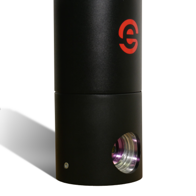
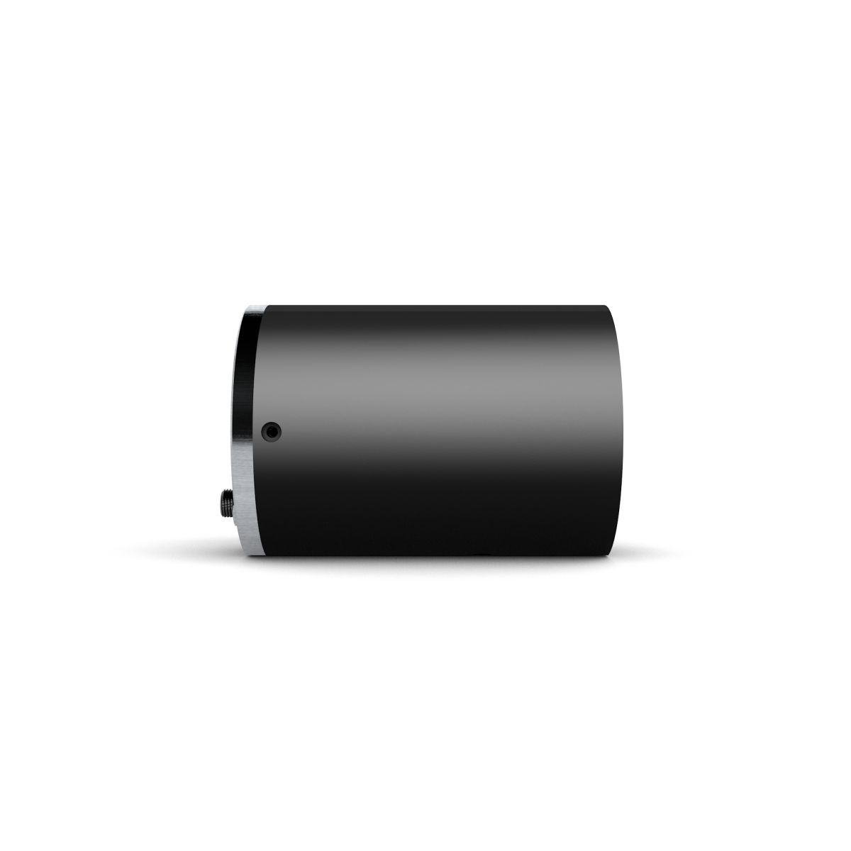
T033 probe — mechanical & optical characteristics
| Probe dimensions (Lh × Wh × Hh) | 93 × 66 × 66 mm (cylindrical Ø66 × 93 mm) |
| Probe weight | 400 g |
| Fiber connector on probe | FC/PC |
| Electrical connector on probe | Push-Pull |
| 90° module — static | Available |
| 90° module — dynamic | Available — exclusive to T033 — ref. 5104781 |
| Probe operating temperature | < 35 °C ambient |
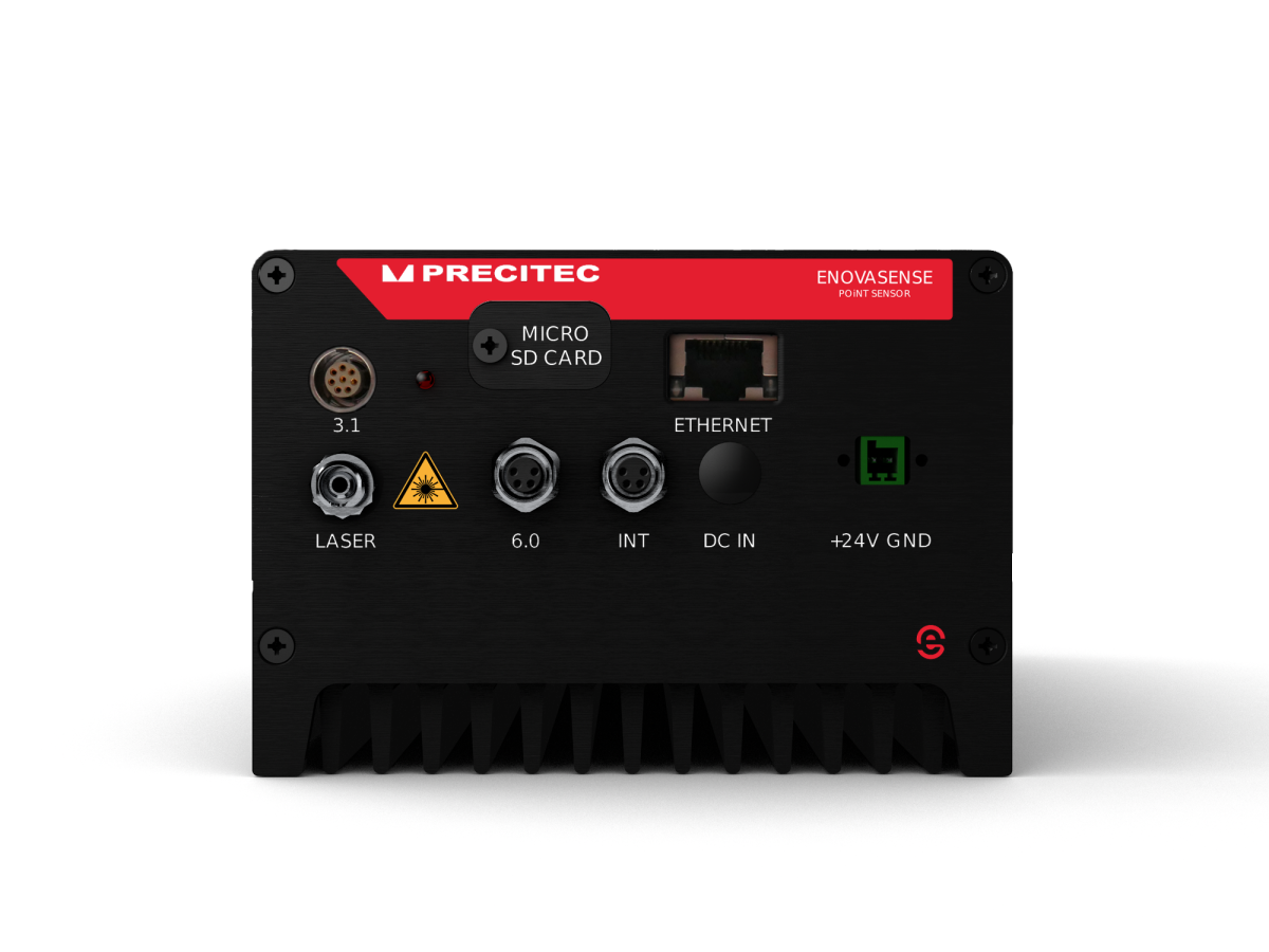
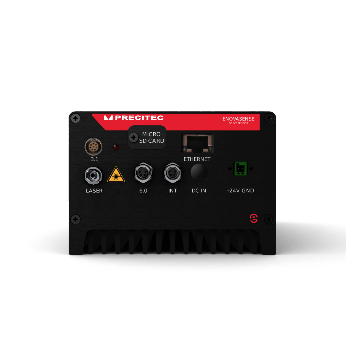
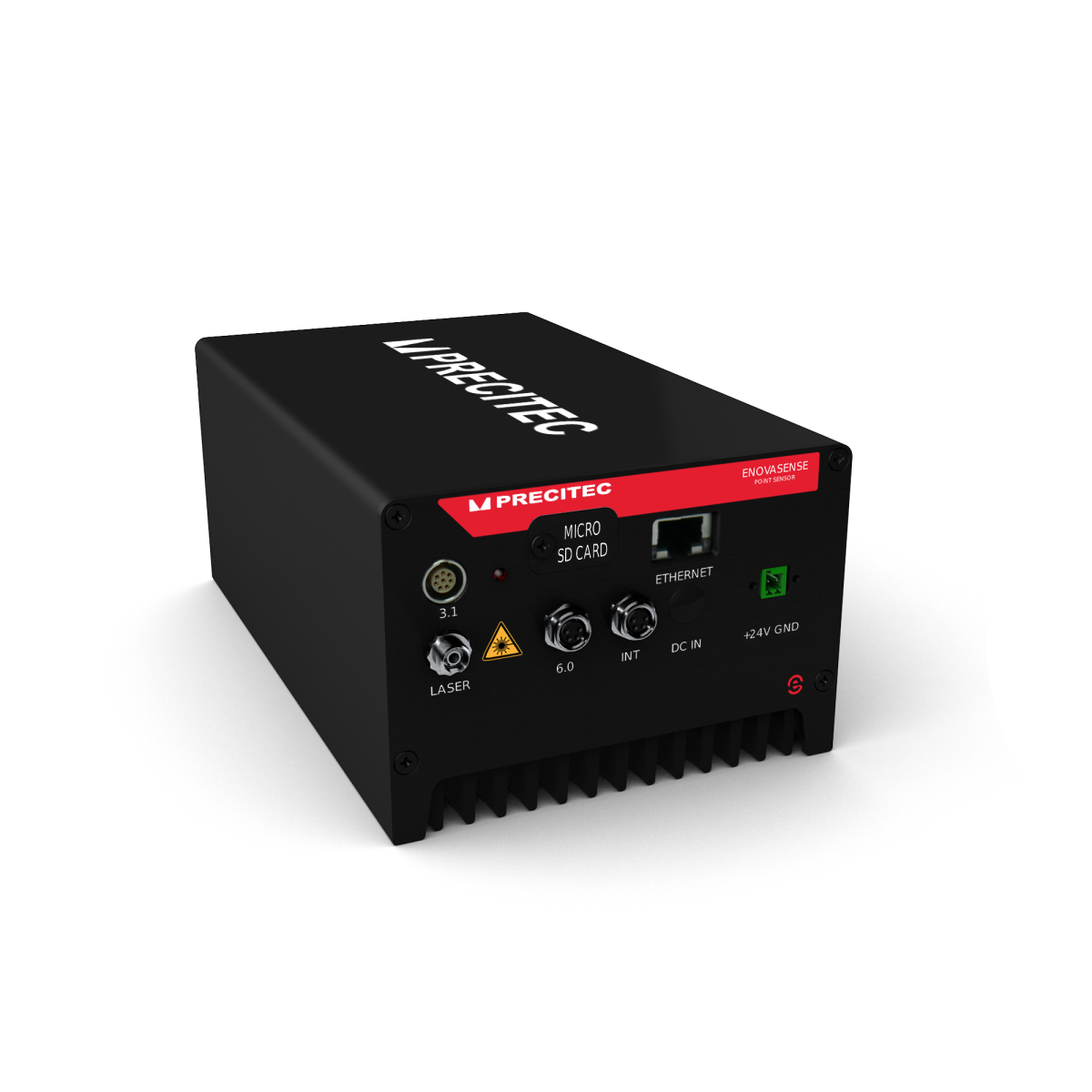
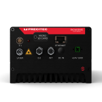
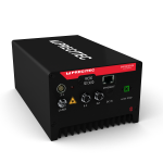
Controller / computing unit
| Computing unit dimensions (Lc × Wc × Hc) | 123 × 200 × 85 mm (single-module C3 version) |
| Computing unit weight | 1.7 kg (single-module C3 version) |
| Power supply | +24 V DC / 3 A max |
| Data interface | Ethernet TCP/IP — CSV export — MES / SPC compatible |
| Safety — interlock connector | M8 — 4 poles — safety loop ready |
| Operating temperature | −5 °C to +50 °C |
| Optical fiber operating temperature | < 100 °C — minimum curvature radius 50 mm |
| Cable operating temperature | < 100 °C |
All values are typical. The actual performance depends on the combination of items selected (module power, optical tool, fiber length) and on the target application. Please contact Enovasense for a performance diagnosis on your specific samples.
06 — Product Structure
A modular sensor — six items to build the system you need
The Point Sensor is structured as a set of six independent articles (plus an optional control station), giving full configuration flexibility. A complete working sensor requires one item from each of the six categories below. For a multichannel system, items 2 to 6 must be ordered in the same quantities as the number of measurement channels.
Figure 2 — The six articles of a complete Enovasense Point Sensor set
Upgrade without replacing. Each item is ordered by a dedicated reference code. You can upgrade a laser power, change a spot size, replace a damaged fiber or extend to a multichannel configuration without replacing the rest of the system.
07 — Available Articles for a T033 Configuration
Full list of references compatible with the T033 probe
① Controller & software suite
One controller is required per system. Choose the size according to the number of channels.
| Reference | Description |
|---|---|
| 5105475 | Single-module controller — for monochannel configurations |
| 5105476 | Hosts up to 5 modules — T033 multichannel |
| 5105478 | Hosts 6 to 10 modules — T033 high-channel-count systems |
② Module (laser + signal acquisition)
Select one module per measurement channel. The choice of wavelength and power depends on the coating material and thickness range.
| Reference | Wavelength | Max power | Typical use |
|---|---|---|---|
| 5105487 | 455 nm | 3 W | Applications absorbing in blue — e.g. specific metallic coatings |
| 5105488 | 455 nm | 10 W | High-power blue — thick or low-absorption coatings |
| 5105480 | 980 nm | 10 W | Most common industrial coatings — metallic, ceramic, thermal spray |
| 5105481 | 980 nm | 20 W | Thicker coatings and low-absorption configurations |
| 5105482 | 980 nm | 150 W | Very thick coatings / short cycle times — reserved configurations |
| 5105486 | 1450 nm | 1 W | Applications absorbing in SWIR — polymers, adhesives |
| 5105484 | 1550 nm | 1 W | Eye-safer SWIR — thin polymer and paint layers |
| 5105483 | 1550 nm | 3 W | Medium-power eye-safer SWIR |
| 5105485 | 1550 nm | 6 W | High-power eye-safer SWIR for thicker polymer layers |
The maximum power of a laser source may vary by up to 30 % below the nominal value.
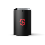
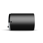
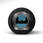
③ Probe — T033
| Reference | Description |
|---|---|
| 5105489 | T033 : Standard optical probe — Ø66 × 93 mm — 400 g — compatible with every optical tool and the dynamic 90° module |
④ Optical tool — T033 (front lens / lens + mirror)
The optical tool defines the spot size on the part and the working distance between the probe and the part. Tools come in three families: simple front lens (screwed or magnetic), Mirror + Lens (90° horizontal emission) and Lens + Mirror (inverted geometry). All references below are compatible with the T033 probe.
| Working distance | Spot size | Simple lens (screwed) | Simple-lens tool (magnetic) | Mirror + Lens tool | Lens + Mirror tool |
|---|---|---|---|---|---|
| 9 mm | 3 mm | 5108000 | 5108002 | — | — |
| 12 mm | 0.3 mm | 5107996 | 5107998 | — | — |
| 20 mm | 0.3 mm | 5104760 | 5105740 | 5105760 | — |
| 20 mm | 0.7 mm | 5104761 | 5105741 | 5105761 | — |
| 20 mm | 2.5 mm | 5104762 | 5105742 | 5105762 | — |
| 20 mm | 4.9 mm | 5104763 | 5105743 | 5105763 | — |
| 20 mm | 6.5 mm | 5104764 | 5105744 | 5105764 | — |
| 40 mm | 0.8 mm | 5104765 | 5105745 | 5105765 | 5105780 |
| 40 mm | 2.3 mm | 5104766 | 5105746 | 5105766 | 5105781 |
| 40 mm | 3.3 mm | 5104767 | 5105747 | 5105767 | 5105782 |
| 40 mm | 10 mm | 5104768 | 5105748 | 5105768 | 5105783 |
| 40 mm | 12 mm | 5104769 | 5105749 | 5105769 | 5105784 |
| 100 mm | 8.3 mm | 5106712 | 5106714 | 5106716 | 5106717 (effective WD 35 mm) |
| 150 mm | 12.4 mm | 5106720 | 5106721 | 5106722 | 5106723 (effective WD 115 mm) |
Working-distance column gives the nominal focal configuration of the lens. For Lens + Mirror tools, the effective distance from the tool's exit aperture to the sample is shorter — indicated in the rightmost column when relevant. Tolerances on the measurement distance range from ±0.5 mm (metallic/ceramic, 20 mm working distance) up to ±20 mm (paints/polymers, 150 mm working distance) depending on the optical tool and the coating family.
Long-working-distance objectives — for stand-off integrations
In addition to the front-lens tools above, three dedicated objectives extend the measurement distance up to 450 mm for hot parts, hard-to-access geometries and safety stand-off requirements.
| Reference | Working distance | Spot size |
|---|---|---|
| 5105899 | 80 mm | 3.3 mm |
| 5105897 | 200 mm | 3.3 mm |
⑤ Optical fiber — T033 (FC/PC ↔ FC/PC)
All T033 fibers are multimode 105 µm core with FC/PC connectors on both ends.
| Reference | Length |
|---|---|
| 5104740 | 2 m |
| 5104741 | 3 m |
| 5104742 | 5 m |
| 5104743 | 10 m |
| 5104744 | 15 m |
| 5105491 | 20 m |
⑥ Electric cable — T033 (Push-Pull LEMO)
One cable per probe. The T033 probe uses a Push-Pull LEMO connector on both ends.
| Reference | Length |
|---|---|
| 5104750 | 2 m |
| 5104751 | 3 m |
| 5104752 | 5 m |
| 5104753 | 10 m |
| 5104754 | 15 m |
| 5105492 | 20 m |
08 — Accessories and options
A number of complementary accessories are available to extend the sensor capability in specific contexts:
| Reference | Accessory |
|---|---|
| 5105888 | Fiber scope — for on-site inspection of the optical fiber ends |
| 5104786 | ISO 17025 Certified reference sample set — for calibration traceability |
| 5104780 | Anti-dust protection window for T033 probe — recommended in dusty spray-booth environments |
| 5105902 | Camera for sample inspection |
| 5105889 | Standoff distance measurement sensor |
| 5105900 | Lens air-blowing system — for contaminated environments (T033) |
| 5105901 | Sample air-blowing system — for contaminated environments (T033) |
| 5105929 | Probe rotation module — for angular scanning inside bores (T033) |
| 5105904 | Point sensor lab mount |
| 5105903 | Automated 1-slot tool changer — for Enovasense magnetic tools |
| 5105940 | Sample rotation table — for integration inside an Enovasense control station |
| 5106481 | HKL table with drawer — underframe for control stations |
| 5105893 | Annual maintenance service — sensor |
| 5105894 | Annual maintenance service — control station |
| 5105895 | Delivery and installation pack |
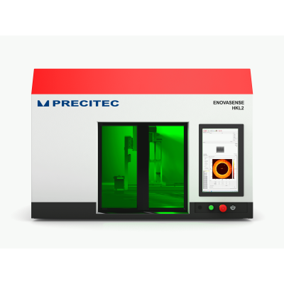
09 — Optional Integration
From sensor to turnkey control station
The T033 Point Sensor can be integrated into one of four Enovasense control stations. These stations include a safe enclosure, an automated positioning system, a PC and a dedicated HMI — turning the raw sensor into a turnkey laboratory, by-the-line or in-line measurement solution. The sensor itself must be ordered separately from the station.
| Reference | Name | Automation | Footprint (L × W × H) | Typical use |
|---|---|---|---|---|
| 5104906 | HKL | 3-axis Cartesian | 825 × 1282 × 943 mm | Lab / R&D / QA benches for flat or simple parts |
| 5105790 | HKL-R | 6-axis robot | 1025 × 1282 × 943 mm | Complex 3D parts — aerospace, turbines, medical implants |
| 5105512 | HKXL | 3-axis + 1-axis loading | 2600 × 2200 × 1250 mm | By-the-line 100% control, large parts such as engine blocks |
| 5105513 | HKXL-IL | In-line 3-axis + loading | 2600 × 2200 × 1250 mm | Full in-line integration with upstream and downstream conveyors |
Need help building a configuration? The T033 probe is compatible with every Enovasense module, every optical tool and every control station. Contact Enovasense with the description of your coating and substrate, your thickness range and your production throughput — we will propose the optimal combination of the six items and, if needed, the appropriate control station.
References
| Réference | Name | Status / Price | Datasheet |
|---|---|---|---|
| C3-W455P1-T33 | Point Sensor 1W 455nm |
Available
On quotation |
English French |
| C3-W1470P1-T33 | Point Sensor 1W 1470nm |
Available
On quotation |
English French |
| C3-W1550P3-T33 | Point Sensor 3W 1550nm |
Available
On quotation |
English French |
| C3-W980P1-T33 | Point Sensor 1W 980nm |
Available
On quotation |
English French |
| C3-W980P10-T33 | Point Sensor 10W 980nm |
Available
On quotation |
English French |