Aplikacje / non-contact coating thickness measurement of coatings on orthopedic implants
01 — Introduction
Bio-active coatings: the interface between a metal implant and living bone
Orthopedic implants such as hip and knee replacements are often coated by plasma spraying — mainly atmospheric plasma spray (APS), and vacuum plasma spray (VPS) for oxygen-sensitive titanium layers — to solve a fundamental biological problem: metal does not naturally bond with living bone. A high-temperature plasma torch propels molten titanium or hydroxyapatite (HAP) — the calcium phosphate mineral that makes up about 70 % of human bone — onto the implant, creating a highly specialised, bio-active surface.
The process transforms a smooth metal component into a rough, porous structure that acts as a microscopic scaffold. This topography triggers osseointegration: living bone cells grow directly into the pores of the coating. By mimicking the chemical and physical properties of natural bone, plasma-coated implants eliminate the need for bone cement and provide a more durable, biological fixation that significantly reduces the risk of loosening over time.
Atmospheric plasma spray (APS) Vacuum plasma spray (VPS) Porous titanium Hydroxyapatite (HAP) Ti + HAP duplex Hip, knee, shoulder, spine
Figure 1 — Implant coating production sequence
The Enovasense measurement can be performed after each spray step and on the final, sterilised device.
Figure 2 — Plasma-sprayed (APS / VPS) coating system on a hip stem (schematic)
02 — Quality Requirements
Why the thickness of Ti and HAP coatings is critical
Coating thickness dictates both the mechanical integrity and the biological success of the implant. It is specified in the device master record, verified in process validation, and increasingly expected by regulators to be checked on final devices.
Too thin: insufficient osseointegration
A titanium or HAP coating that is too thin may not provide enough surface area or structural depth for bone cells to achieve secure osseointegration. The fixation remains weak and the implant is exposed to premature loosening — the leading cause of revision surgery.
Too thick: delamination and third-body wear
Conversely, an over-thick coating becomes prone to delamination or cracking under the cyclic stresses of daily movement. Excessively thick HAP layers are particularly brittle: they may resorb or flake off into the joint space, generating third-body wear that destroys the bearing surfaces of the implant.
Regulatory pressure towards 100 % control on final devices
Orthopedic implants are high-value, precision-engineered devices and health authorities push for high-frequency control of coating processes. The FDA, for instance, recommends that coating testing be performed on final sterilised devices from multiple lots. This excludes destructive techniques — and any technique that touches the sterilised part.
|
90 – 200 µm
HAP thickness range covered in the feasibility study on six hip implants
|
1 s
Per measurement point, non-contact, directly on the coated part — no uncoated reference needed
|
|
Cg 7.30 / Cgk 7.14
Type 1 MSA gauge capability on a 113 µm HAP coating — more than five times the 1.33 threshold
|
100 %
Inspection of final sterilised devices becomes realistic — sterility preserved
|
03 — Measurement Challenges
Why non-destructive, non-contact measurement is a must
Plasma-sprayed implant coatings — APS or VPS — combine every difficulty at once: a rough, porous surface; a complex, curved, often small geometry; a sterile final state; and a destructive reference method that consumes the very devices it is supposed to release.
Cross-section microscopy: the reference that destroys the implant
Metallographic cross-section remains the validation reference, but each measurement sacrifices a finished, high-value implant and documents only a few locations. It cannot be applied to final sterilised devices from multiple lots on a routine basis.
Contact probes: contamination, damage and roughness bias
Eddy-current or magnetic-induction probes bring a contamination risk on sterilised parts and may damage the brittle HAP surface. They also read inaccurately on such rough surfaces — the probe rests on the highest peaks and overestimates the average thickness — and struggle with the curved geometries and small features of hip stems and acetabular cups. Eddy current is in any case limited to the non-conductive HAP layer and cannot measure titanium on titanium.
Differential 3D profilometry: two measurements, multiplied uncertainties
3D profilometry is non-contact and non-destructive, but it only captures the outer skin of the part and requires a prior scan of the uncoated implant. This before/after operation multiplies the measurement uncertainties and demands an extremely precise repositioning — almost impossible given the part geometry, the surface roughness, thermal expansion and the environmental sensitivity of the instrument. It is also slow and cannot be automated on sterilised devices.
Figure 3 — Differential profilometry vs direct photothermal measurement
04 — Technology Comparison
Why laser photothermal radiometry is the right solution for coated implants
Enovasense’s patented laser photothermal radiometry resolves the conflict between sterile integrity and precise characterisation of porous surfaces. A modulated laser beam heats the coating by a few degrees; the thermal wave diffuses into the layer and reflects at the coating–substrate interface; an infrared detector captures the thermal response, whose decay is physically governed by the depth of the layer. The thickness is computed instantly from the coated part alone, in a single 1-second step, entirely bypassing the before/after comparison.
Because the method relies on thermal diffusion and averages over a 2 – 3 mm spot, it is unaffected by the bumpy topography of plasma-sprayed surfaces that makes contact probes sit on the highest peaks, and it measures titanium on titanium as readily as HAP on titanium. Non-contact at a working distance of several centimetres, it allows 100 % inspection of final sterilised devices without manual alignment or baseline subtraction.
“[Enovasense technology] allows us to obtain precise and reliable measurements, two attributes that are impossible to combine with conventional techniques.”
HTI Technologies
DeviceMed Magazine, February 2022
| Criteria | Enovasense laser photothermal | Eddy current / magnetic induction | Differential 3D profilometry |
|---|---|---|---|
| Contact | Non-contact | Contact | Non-contact |
| Sterility of the implant | Preserved | Compromised — contact needed | Hard — multiple handlings |
| Ti and HAP coatings | Both | HAP only | Both |
| High surface roughness | No impact — averaged over the spot | Overestimates — probe on the highest peaks | Shadowing effect |
| Complex geometries | No impact | Impacted — curvature, proximity to edges | Complex realignment |
| Measurement time | 1 s per point | 1 s per point | Slow — alignment, scans, analysis |
| In-situ implementation / automation | Simple | Difficult — contact needed | Impossible |
| 100 % inspection | Realistic | Impossible | Impossible |
05 — Metrological Performance
Feasibility study: HAP coatings on six hip implants
The study was performed on six titanium-based hip implants carrying HAP coatings at thickness levels from 90 to 200 µm. An Enovasense Point sensor was used with the following parameters: 980 nm wavelength, 10 W maximum laser power, 1 s measuring time, 35 mm probe-to-part distance and a 2.6 mm laser spot. The sensor was mounted in a 3-axis control station and a 2D map of each implant was acquired with a 1 mm step in both directions.
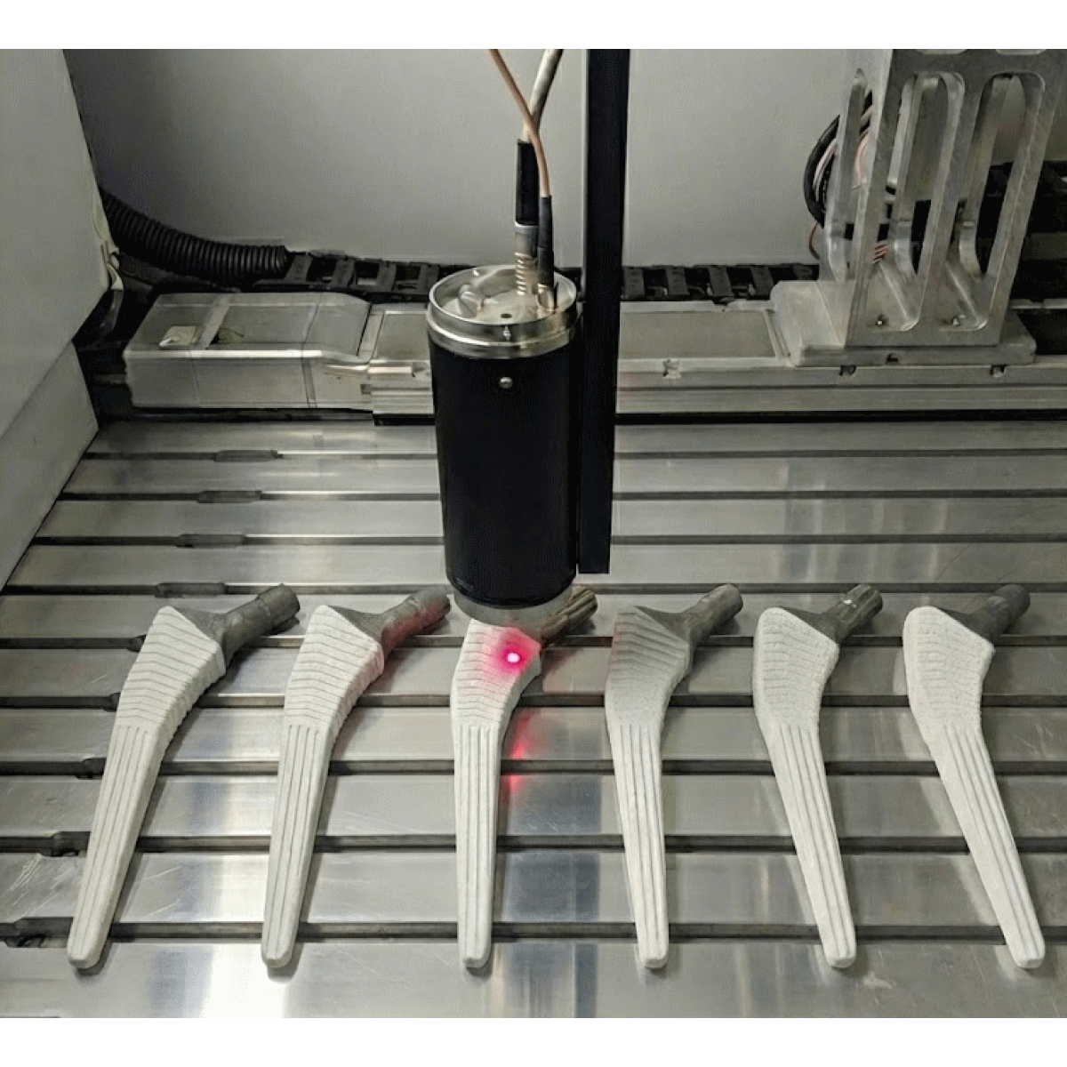
Enovasense Point sensor mapping HAP-coated hip implants in a 3-axis control station
Full mapping of every implant, including small features
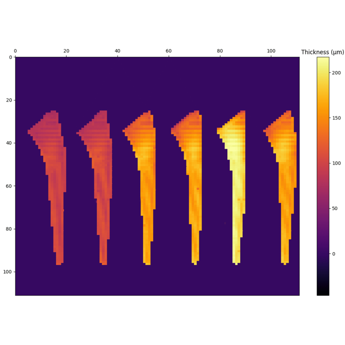
HAP coating thickness maps of the six hip implants, 1 mm step (Enovasense Point sensor)
The maps show that the laser photothermal point sensor measured the coating thickness at every position of the hip implants, including tiny areas — neck, collar, edges of the coated zone — where contact or profilometric methods are blind.
Accuracy: correlation with destructive cross-sections
The photothermal results were then correlated with destructive cross-section microscopy performed at 10 positions per sample. For both techniques, the mean value and the standard deviation per implant were used for the intercomparison.
Figure 4 — Mean HAP thickness per implant: laser photothermal vs cross-section
Mean HAP coating thickness per sample, photothermal mapping vs destructive cross-section at 10 positions. Δ = photothermal − cross-section.
The values are very close between the two techniques: within a few microns on five of the six implants, i.e. well inside the dispersion of a plasma-sprayed coating. The larger gap on sample F (17 µm) is consistent with the local variability of a rough HAP layer when 10 cross-section positions are compared with a full-surface average.
Repeatability and gauge capability (type 1 MSA)
Repeatability tests demonstrate the high stability of the technology, with consistent results across repeated measurements at identical locations. To assess the intrinsic performance of the measurement system, a type 1 measurement system analysis was conducted on a representative sample with a reference value of 113.00 µm, under controlled conditions.
Figure 5 — Type 1 gauge study on a 113 µm HAP coating
Run chart of the repeated measurements against the reference value (green) and the measured mean (dashed red). Schematic rendering consistent with the study statistics.
- Bias: the p-value (0.0065) is below 0.05, so the bias is statistically significant — but it amounts to only +0.22 µm (mean 113.22 µm against a 113.00 µm reference), negligible for a 100 µm-class coating.
- Capability: the capability indices Cg = 7.30 and Cgk = 7.14 are extremely high, far above the 1.33 acceptance limit: the measurement dispersion is tiny relative to the coating tolerance.
Performance figures correspond to the configuration used in this study. Actual performance depends on the optical system selected, the coating (Ti, HAP, duplex) and its thickness range. A dedicated calibration is built per coating system.
06 — Industrial Integration
Integrating Enovasense sensors in the implant coating workflow
The Enovasense probes are compact, non-contact and tolerant to distance and angle variations, which suits both the coating shop and the clean environment of final inspection. Three integration levels cover the needs of implant manufacturers and coating subcontractors.

Referencje
| Referencja | Nazwa | Status / Cena | Karta katalogowa |
|---|---|---|---|
| ARTICLE - IMPLANTS | Non Contact Thickness Measurement of Coatings on Orthopedic Implants |
Dostępne
Wycena indywidualna |
English Français |
Dokumenty
| Typ | Nazwa | Pobierz |
|---|---|---|
| Application | Des équipements de revêtement plasma sous haute surveillance | Français |

 English
 Deutsch
 Español
 Français
 Italiano
 日本語
 한국어
 中文