Applications / in-line thickness measurement of electrical steel insulation
01 — Introduction
Insulation coatings: a few microns that decide the efficiency of motors and transformers
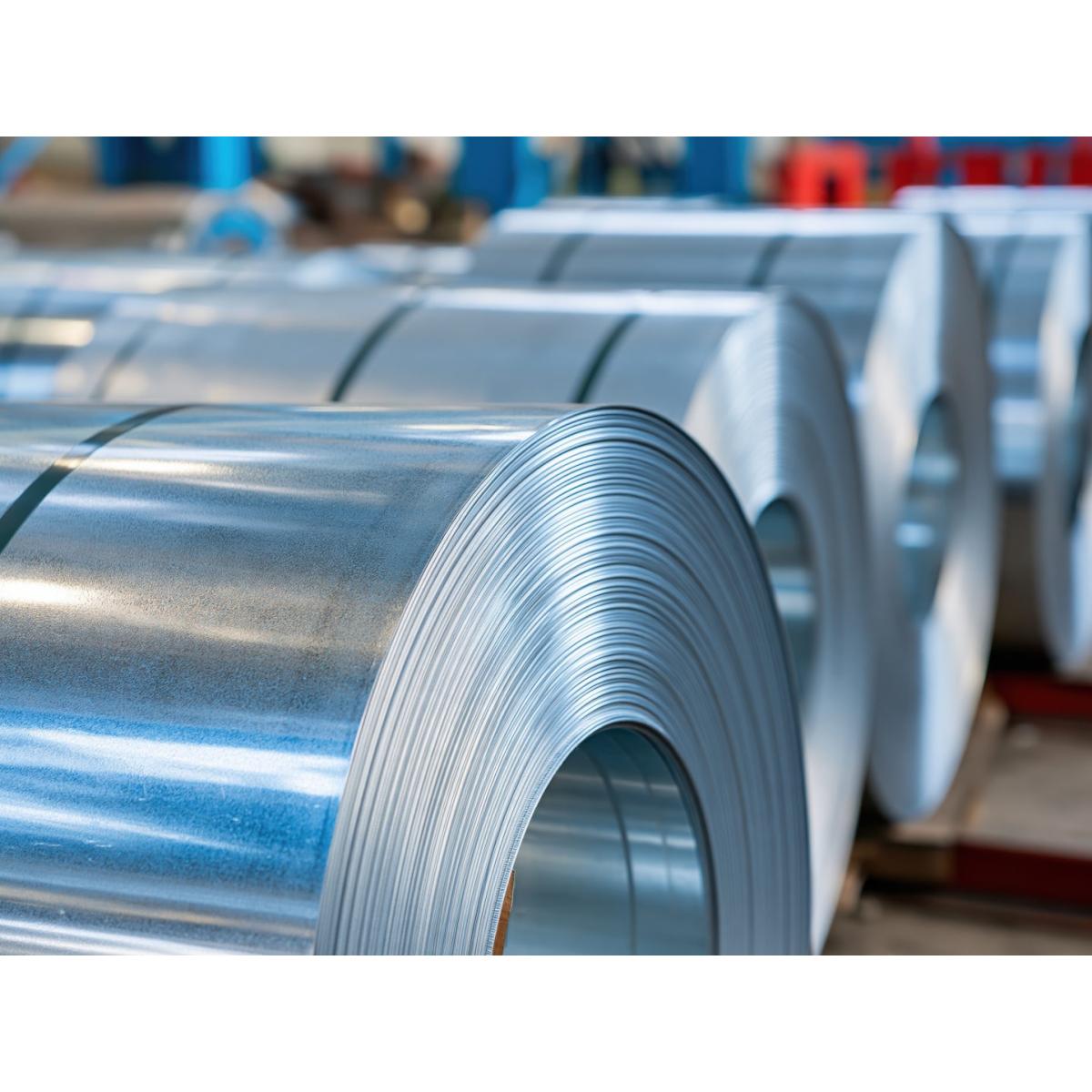
Electrical steel is the magnetic core of every transformer, electric motor and generator. To limit eddy-current losses, the core is built from thin laminations — typically 0.20 to 0.65 mm thick — stacked or wound on top of each other. Each lamination must be electrically insulated from its neighbours. This is the job of the insulation coating, a thin layer applied on both faces of the strip at the end of the steelmaking process.
Two families of electrical steel are produced, each with its own coating architecture:
Grain-oriented (GO) Non-oriented (NO / NGO) Self-bonding varnishes
Grain-oriented steel, used in transformers, carries a forsterite film formed during high-temperature annealing from an MgO separator, topped by a phosphate-based tension coating. Non-oriented steel, used in motors and generators — including traction motors for electric vehicles — receives a single insulating varnish. Depending on the application, these coatings are inorganic, organic or hybrid (for example classes C3, C5 and C6 according to ASTM A976), and increasingly chrome-free. A growing share of NO strip also receives self-bonding varnishes that replace welding or interlocking in the lamination stack.
In all cases, the coating is applied as a liquid by roll coaters, then dried and cured in a continuous oven before coiling.
Coating classes and typical products
Insulation coatings are classified by ASTM A976 (classes C-0 to C-6), with equivalent EC designations in IEC 60404-1-1. The classes most often applied on coating lines are listed below, with examples of commercial products measured or targeted by Enovasense sensors.
| Class (ASTM A976 / IEC) | Nature | Typical use |
|---|---|---|
| C-2 | Glass-like forsterite film formed from an MgO annealing separator | Grain-oriented steel, under the tension coating |
| C-3 | Organic varnish, including self-bonding varnishes | Motors and generators, bonded lamination stacks |
| C-4 | Inorganic coating from chemical treatment of the surface (e.g. phosphate) | Grain-oriented tension coatings, annealed laminations |
| C-5 / EC-5 | Inorganic or hybrid coating with inorganic fillers, high resistance | Laminations requiring stress-relief annealing or welding |
| C-6 / EC-6 | Organic coating with inorganic fillers | High-power rotating machines, high insulation level |
Examples of commercial coatings in this field (non-exhaustive list):
- Rembrandtin / Kansai Helios — REMISOL® electrical steel coatings, e.g. REMISOL EB 5308, EB 5320 (chrome-free, grain-oriented steel), EB 5340, EB 5350S and EB 5002M.
- Axalta — Voltatex® electrical steel coatings and bonding varnishes, e.g. Voltatex 1175W, 1230 and 1250V.
- ELANTAS (ALTANA) core plate insulation varnishes.
- Kluthe insulating coatings for electrical steel.
- Phosphate-based tension coatings for grain-oriented steel, such as CARLITE®-type coatings, and in-house formulations of steel producers.
All trademarks belong to their respective owners. Their mention identifies the type of coating concerned and does not imply any endorsement or partnership.
Figure 1 — Annealing and coating line sequence
02 — Quality Requirements
Why coating thickness must be controlled on both faces, over the full strip
The insulation coating sits in a narrow process window. Typical dry thicknesses range from a few tenths of a micron to about 10 µm per face, and specifications are often expressed as a coating weight in g/m². Deviations on either side of the window have direct consequences on the final electrical machine.
Too thin: insulation failure
A coating that is locally too thin no longer guarantees the interlaminar resistance. Electrical contact between laminations creates short-circuit paths in the core, which increase eddy-current losses and local heating. For self-bonding varnishes, an insufficient layer also weakens the bond strength of the stack.
Too thick: lower stacking factor and processing issues
Every extra micron of coating is non-magnetic material inside the core. An excessive coating reduces the stacking factor — the share of steel in the core volume — and therefore the efficiency of the motor or transformer. It can also degrade punchability, weldability and adhesion, and increases coating consumption.
Roll-coater drift and chrome-free reformulation
Roll wear, viscosity changes, roll-gap or speed variations and edge effects all modify the applied thickness across the width and along the coil. At the same time, the industry-wide move towards chrome-free formulations forces producers to requalify their coating weights. Only a dense measurement across the strip width, on both faces, reveals these deviations before the coil is shipped.
|
0.5 – 9 µm
Typical thickness range of insulation coatings measured by Enovasense sensors
|
R² = 0.96
Correlation with a contact reference gauge
|
|
σ = 0.09 µm
Repeatability on a 5.4 µm coating (10 measurements, same point)
|
1 s
Measurement time per point, without contact
|
03 — Measurement Challenges
Why conventional methods leave the coating line blind
Insulation coatings are thin, low-density, often transparent, and applied on a ferromagnetic substrate moving at high speed. Most steel producers still rely on laboratory methods performed on samples cut at the coil end.
Gravimetric strip-and-weigh: accurate but destructive and slow
The coating weight is determined by weighing a sample before and after chemical stripping of the coating. The method is the usual reference, but it is destructive, takes time, and gives one value per sample — typically at the head or tail of the coil. A drift occurring in the middle of the coil goes unnoticed.
Insulation-resistance tests: a functional check, not a thickness
Surface insulation resistance tests (such as the Franklin test) verify that the coating insulates, but do not give its thickness. They are performed offline and do not tell the operator how to adjust the roll coater.
Contact and inline gauges: limited by the coating itself
Handheld magnetic-induction or eddy-current probes give a thickness, but require contact and remain spot checks on cut samples. Inline gauges based on X-ray absorption or on fluorescence face other limits: the low density and variable composition of the coatings for the former, and the need for a fluorescent or pigmented component for the latter — which excludes many inorganic and transparent coatings.
The case for non-contact thickness mapping
- Every coil is measured, not only its head or tail sample.
- Both faces are controlled, so a deviation on one roll coater is identified immediately.
- Organic, inorganic and hybrid coatings are measured with the same principle, whether transparent or pigmented.
- Closed-loop correction of the roll coater becomes possible, reducing coating consumption and off-spec material.
04 — Technology Comparison
Why laser photothermal radiometry fits insulation coatings
Enovasense’s patented laser photothermal radiometry measures the coating through its thermal properties. A modulated laser beam generates a thermal wave at the surface; an infrared detector captures the heat that diffuses back; the coating thickness is extracted from the phase of the thermal response. Because insulation coatings and steel have very different thermal properties, the contrast is strong even for sub-micron layers. The method is fully non-contact, non-destructive, and does not depend on the colour or transparency of the coating.
| Criteria | Enovasense laser photothermal | Contact magnetic-induction probe | Gravimetric strip-and-weigh |
|---|---|---|---|
| Non-contact measurement | Yes | No — probe contact required | No — sample is cut and stripped |
| Non-destructive | Yes | Yes — on cut samples | No |
| Organic, inorganic and hybrid coatings | Yes — one calibration per coating | Yes | Yes — stripping chemistry per coating |
| Thickness mapping | Yes — dense scanning across the strip | Limited — point by point | No — one average per sample |
| Automation on the line | Possible — remote optical head | No | No |
| Time to result | ≈ 1 s per point | Minutes — sampling and handling | Tens of minutes or more |
| Closed-loop process feedback | Yes — data to L2 / MES | Limited | No |
05 — Metrological Performance
Case study: insulation coatings from an integrated steel producer
An integrated steel producer supplied coated strip samples from its electrical steel lines, covering the C3, C5 and C6 classes at several coating weights. The samples were measured with an Enovasense sensor in a laboratory control station, without contact, using the following configuration:
| Laser wavelength / maximum power | 980 nm / 10 W |
| Measuring head | T033 |
| Working distance / spot diameter | 33 mm / 2.3 mm |
| Measurement time per point | 1 s |
The figures reported below correspond to the measurement configuration used during this study. Actual performance on a given application depends on the optical system selected, on the coating formulation and on its thickness range.
Accuracy: correlation with a contact reference gauge
The Enovasense results were compared with thickness values obtained with a contact magnetic-induction / eddy-current gauge on the same samples. The two methods show a linear correlation with R² = 0.96 across the 2–8 µm range covered by the reference measurements, with a single regression line across the three coating classes.
Figure 2 — Enovasense thickness vs contact reference gauge
Each point is the average thickness of a measurement zone, coloured by coating class. Dashed line: linear regression on all classes.
Repeatability
Ten successive measurements were taken at exactly the same point of a C5 sample. The mean thickness is 5.41 µm with a standard deviation of 0.09 µm, i.e. a relative standard deviation of 1.7 % — well below the typical tolerance of a coating-weight specification.
Figure 3 — Repeatability: 10 successive measurements at the same point
Dashed line: mean value. Shaded band: ± 1 standard deviation.
Tolerance to the working distance
Strip flatness, flutter and pass-line variations change the distance between the sensor and the surface. The sample was measured while varying this distance around its nominal value: the measurement bias remains negligible within a ±5 mm window, which is the recommended working tolerance for this optical configuration.
06 — Industrial Integration
From laboratory mapping to inline control
Enovasense supports steel producers and coil processors at every stage, from the qualification of a new formulation to the continuous control of a production line.
At-line laboratory control
Coil-end samples are placed in an Enovasense control station that maps the coating thickness on both faces automatically. The result replaces or complements gravimetric tests in minutes rather than hours, and is the fastest way to qualify chrome-free formulations or new coating weights.
Inline measurement
On the line, Enovasense measuring heads are installed after the curing oven, on one or both faces of the strip, at fixed positions or on a traversing frame. Air is blown on the exit window to protect the optics. The working distance of several centimetres keeps the head away from the strip, and the ±5 mm distance tolerance absorbs pass-line variations. Results are sent in real time via Ethernet (TCP/IP) to the line automation, L2 or MES systems, for coil documentation and roll-coater feedback.
Video — Enovasense inline measurement on a coil coating line
Continuous, non-contact coating thickness measurement on a moving steel strip. This installation is on a coil coating line; the same measuring principle and integration approach apply to the annealing and coating lines of electrical steel.
Deployment steps